Nestable Container With Uniform Stacking Features

a technology of nested containers and features, applied in the field of containers, can solve the problems of uniform rim spacing, and difficult densification of non-uniformly stacked containers, and achieve the effects of facilitating reliable densification, facilitating separation of nested containers, and increasing the effective thickness of the flang

Active Publication Date: 2011-11-10
GRAPHIC PACKAGING INT
View PDF11 Cites 21 Cited by
  • Summary
  • Abstract
  • Description
  • Claims
  • Application Information

AI Technical Summary

Benefits of technology

[0010]In one embodiment, the flange is divided into a relatively thick radially inner portion and a relatively thin radially outer portion so that the thick portion uniformly engages the corresponding thick portion of adjacent containers in a nested stack, and the relatively thin portions of adjacent containers are thereby spaced to facilitate reliable denesting.
[0011]In another embodiment, the flange is divided into two portions with an upstanding portion along the radially inner edge of the flange and a radially extending portion along a radially outer portion. The upstanding portions of containers in a nested stack engage, and thereby separate, adjacent containers to allow the radially outer portion of the flanges to be uniformly spaced to facilitate reliable denesting.
[0013]In still other embodiments, a rolled or folded peripheral edge of each flange increases the effective thickness of the flange so that the remainder of the flanges of adjacent containers in a nested stack are spaced to facilitate reliable denesting. The fold or roll in the peripheral edge of the flange of each container may define a curved cam-like surface that facilitates separation of the nested containers.
[0014]In yet other embodiments, a flange may be formed with a groove or depression extending along the circumference of the flange. A rolled or folded peripheral edge may extend from the outer rim of the flange and at least partially underneath the depression to facilitate denesting of stacked containers and to increase the effective thickness of the flange.
[0015]In yet other embodiments, a container may be formed with a multi-angled sidewall. The container sidewall may be formed of a lower sidewall extending from a container base at a first angle, and an upper sidewall extending from a plane parallel to the container base at a second, greater angle. A ridge is defined where the upper and lower sidewalls meet. The ridge and the multi-angled sidewall may increase the container's resistance to forces applied perpendicular to the container base, and thus minimize deformation. Further, the sidewall angles may minimize lateral movement of individual containers in a stack and provide enhanced nesting / denesting capabilities.
[0016]In an additional embodiment, a method is used to form a paperboard container with a rolled downturned flange. Optionally, the flange can include a circumferential depression or groove. The flange of this embodiment generally includes a downwardly sloping shape to help resist bending and a folded-under rolled section to increase strength and to convey a perception of a stronger, thicker flange. The presence of a groove increases the flange thickness and aids in the removal of containers from a stack. The groove and flange in combination may also help seal lids to the container.

Problems solved by technology

Conventional pressed paperboard trays and plate containers, however, typically do not have uniform rim spacing and / or thickness, which leads to non-uniform stacking.
Non-uniformly stacked containers are difficult to denest, or manually separate, which adds cost and time to use of the containers.
Other aspects of conventional containers may also hinder denesting.

Method used


Image

  • Nestable Container With Uniform Stacking Features
  • Nestable Container With Uniform Stacking Features
  • Nestable Container With Uniform Stacking Features

Examples


first embodiment

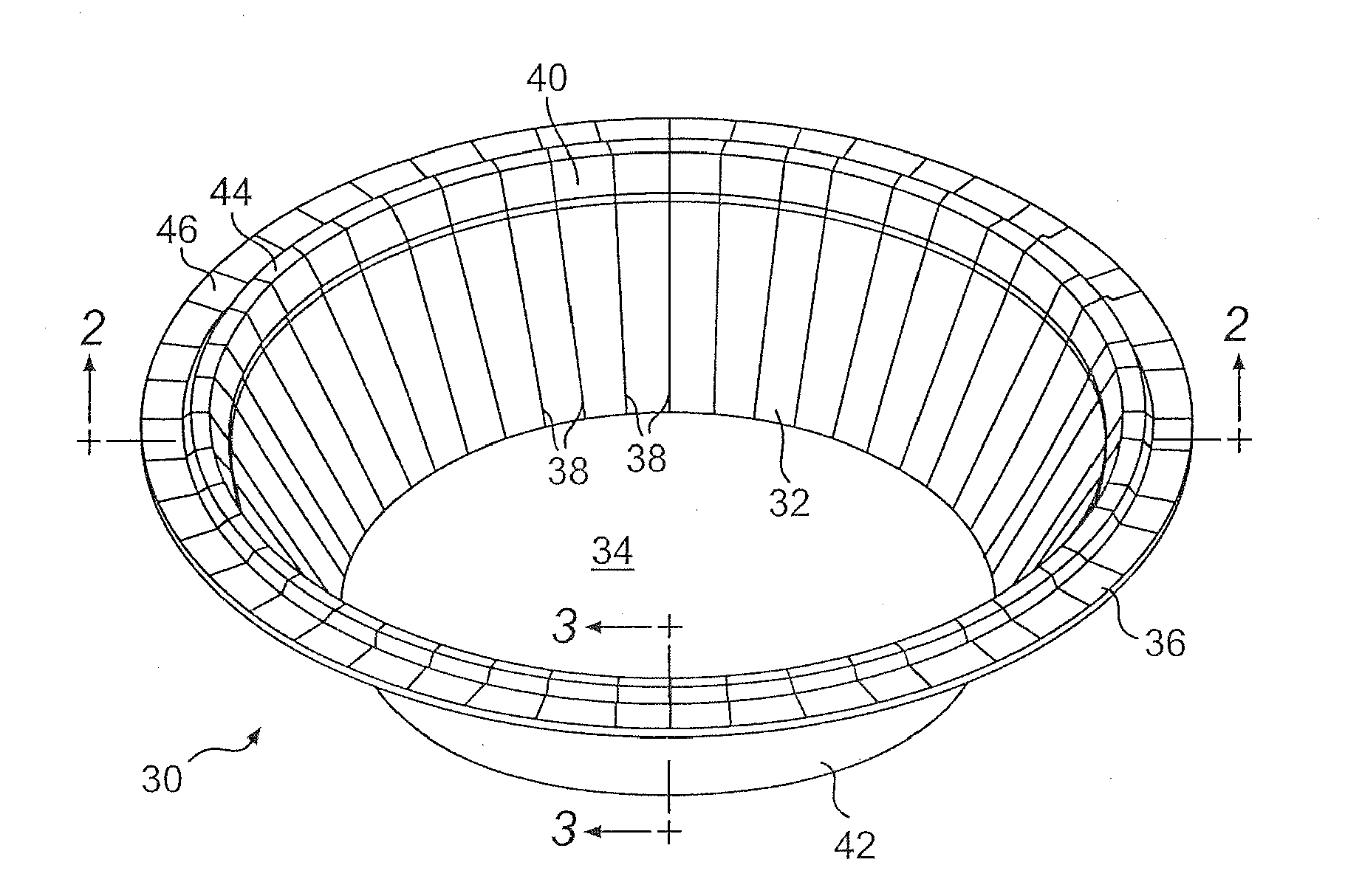
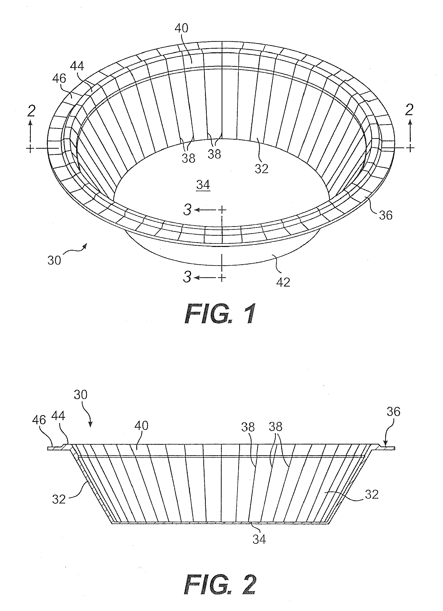
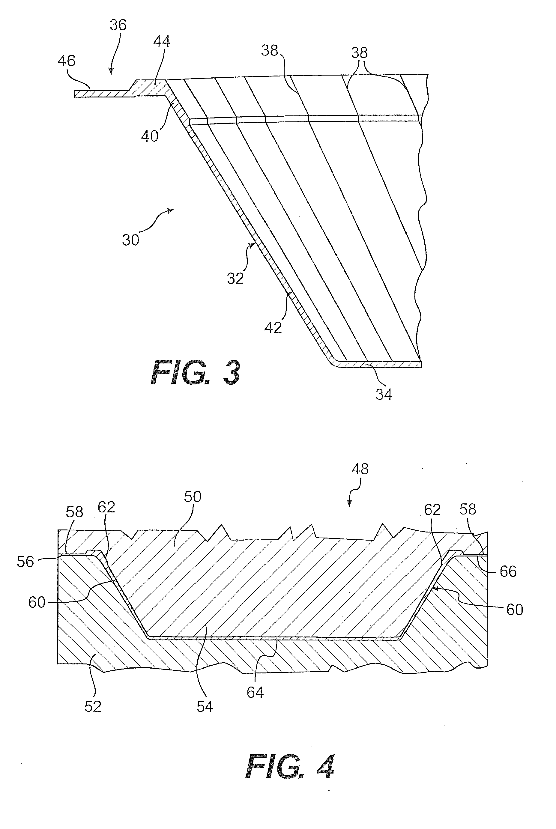
[0090]FIGS. 1-3 illustrate a container 30 having a downwardly tapering frustoconical sidewall 32 that is integrally continuous along its bottom edge with a flat circular bottom wall 34, and along its top edge with a radially outwardly directed horizontal flange 36. The sidewall 32 and the flange 35 have a plurality of radially directed pleats 38. As will be explained in more detail below, an upper peripheral area 40 of the sidewall 32 is relatively thick in comparison to the remaining lower portion 42 of the sidewall 32 to facilitate alignment of nested containers of the same construction. Similarly, the flange 36 has a relatively thick radially inner peripheral portion 44 and a relatively thin radially outer peripheral portion 46.

[0091]The container 30 may be formed from a flat circular blank (not shown) of material, such as paperboard, with the circular blank of material having a plurality of radially directed uniformly spaced score lines formed therein, with the score lines radia...

second embodiment

[0101]FIGS. 7-10 illustrate a container 102. Referring to FIGS. 7 and 8, the container 102 is similar to the container 30 shown in FIGS. 1 and 2 in that it includes a generally frustoconical sidewall 104 that is integrally continuous along its lower edge with a flat circular bottom wall 106, and along its upper edge with a ring-like outwardly directed radial flange 108. Radiating pleats 109 extend across the sidewall 104 and the flange 108. In this embodiment, the sidewall 104 is deformed during the forming process to define an annular recess 110 in the inner surface of the sidewall 104 that is generally V-shaped in cross section, and a generally V-shaped ring-like protrusion 112 in the outer surface of the sidewall 104. The flange 108 is defined by a radially inner upstanding wall portion 114 and a radially outer flat radial ring-like portion 116.

[0102]FIG. 9 illustrates a forming operation of the container 102 in a die set 118. The die set 118 has a forming punch 120 and a forming...

third embodiment

[0104]FIGS. 11-16 illustrate variants of a container 142 and a method of making the container. Referring to FIGS. 11-13, the container 142 is similar to the container 30 shown in FIGS. 1-2 in that it includes a frustoconical sidewall 144 integrally continuous along a bottom edge with a circular flat bottom wall 146 and along a top edge with a ring-like radially outwardly directed flange 148. Radiating pleats 149 are formed in the sidewall 144 and the flange 148 as described in previous embodiments.

[0105]Referring to FIGS. 11-15, with specific reference to FIGS. 14 and 15, the flange 148 of the container 142 includes a plurality of deformations, namely convex hemispherical protrusions 150 extending from the bottom side of the flange 148, and concave indentations 152 defined in the top of the flange 148. The protrusions 150 separate the flanges 148 of adjacent like containers 142 in a nested stack of containers 142. The protrusions 150 are illustrated as generally hemispherical, altho...


PUM


Abstract

Various embodiments of flanged containers that can be stacked in a nested relationship are disclosed so as to provide uniform spacing between the containers to facilitate reliable denesting thereof. The flanges and / or sidewalls of the containers may be provided with features that facilitate alignment and uniform spacing of the nested containers so that a denesting apparatus can reliably denest the containers. Other containers include sidewalls divided into two sections that serve to stabilize stacked container.

Description

CROSS-REFERENCE TO RELATED APPLICATIONS[0001]This application is a divisional of U.S. patent application Ser. No. 10 / 986,621, filed Nov. 12, 2004, which application claims the benefit of U.S. Provisional Application No. 60 / 518,908, filed Nov. 11, 2003, U.S. Provisional Application No. 60 / 564,045, filed Apr. 20, 2004, U.S. Provisional Application No. 60 / 564,443, filed Apr. 21, 2004, and U.S. Provisional Application No. 60 / 599,892, filed Aug. 9, 2004.INCORPORATION BY REFERENCE[0002]The disclosures of U.S. patent application Ser. No. 10 / 986,621, filed Nov. 12, 2004, U.S. Provisional Application No. 60 / 518,908, filed Nov. 11, 2003, U.S. Provisional Application No. 60 / 564,045, filed Apr. 20, 2004, U.S. Provisional Application No. 60 / 564,443, filed Apr. 21, 2004, and U.S. Provisional Application No. 60 / 599,892, filed Aug. 9, 2004, are hereby incorporated by reference for all purposes as if presented herein in their entirety.BACKGROUND[0003]1. Technical Field[0004]The technical field relat...

Claims


Application Information

Patent Timeline
Patent Type & Authority Applications(United States)
IPC IPC(8): B65D21/00B65D1/26B65D1/34B65D21/02
CPCB65D1/34B65D21/0233B31B2201/223B65D21/0212B65G59/066B31B1/00B31B50/592B31B50/00B65G59/108B31B2100/00B31B50/73
Inventor WNEK, PATRICK H.MARX, RONALD P.KLUZ, JAMESO' HAGAN, BRIAN R.MIDDLETON, SCOTT W.
Owner GRAPHIC PACKAGING INT
Why Eureka
Try Eureka