Imaging Through Silhouetting

a technology of silhouetting and imaging, applied in the field of imaging systems, can solve the problems of additional signal interpretation problems, subject becomes harder and harder to image, and the analysis of the image cannot determine if a subject is present, so as to achieve the effect of improving the effectiveness of imaging using microwaves and adding effective thickness

Active Publication Date: 2008-07-03
AGILENT TECH INC
View PDF33 Cites 6 Cited by
  • Summary
  • Abstract
  • Description
  • Claims
  • Application Information

AI Technical Summary

Benefits of technology

[0008]Imaging using microwaves is improved by placing a reflective surface behind the subject being imaged and within the range of the imager. The use of a reflective surface produces a silhouette of the subject which may be analyzed, and also adds effective thickness to translucent subjects which provides additional information for analysis.

Problems solved by technology

As receive elements are only capable of detecting radiation received at the element's location, active microwave imaging systems are highly dependent on the geometric components of the subject being imaged, and as such they are prone to “shadowing” or areas where no information is available.
If the receiver does not receive a signal from a point or voxel (a three dimensional space within a larger scanned volume) in space, then no image appears at that voxel, and analysis of the image can not determine if a subject is present or not.
Therefore, some materials are translucent, and this translucence can cause additional signal interpretation problems.
However, as the thickness of the material is reduced, the subject becomes harder and harder to image.

Method used


Image

  • Imaging Through Silhouetting
  • Imaging Through Silhouetting
  • Imaging Through Silhouetting

Examples


Embodiment Construction

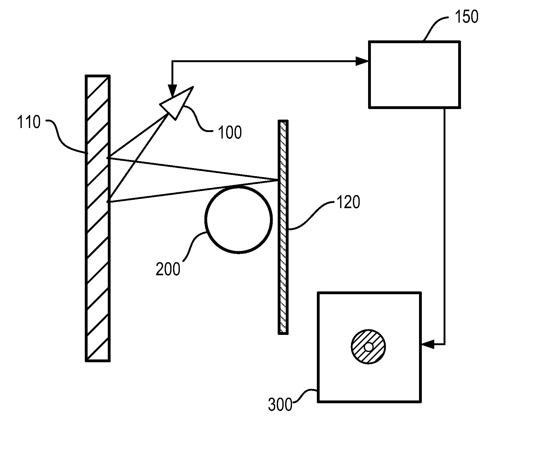
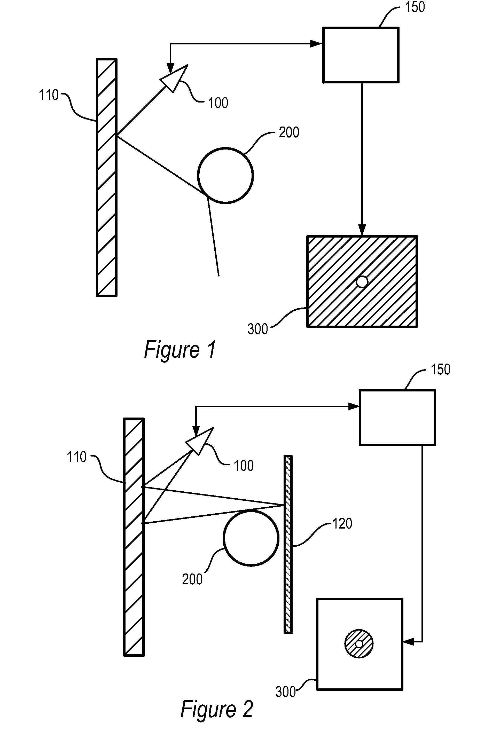
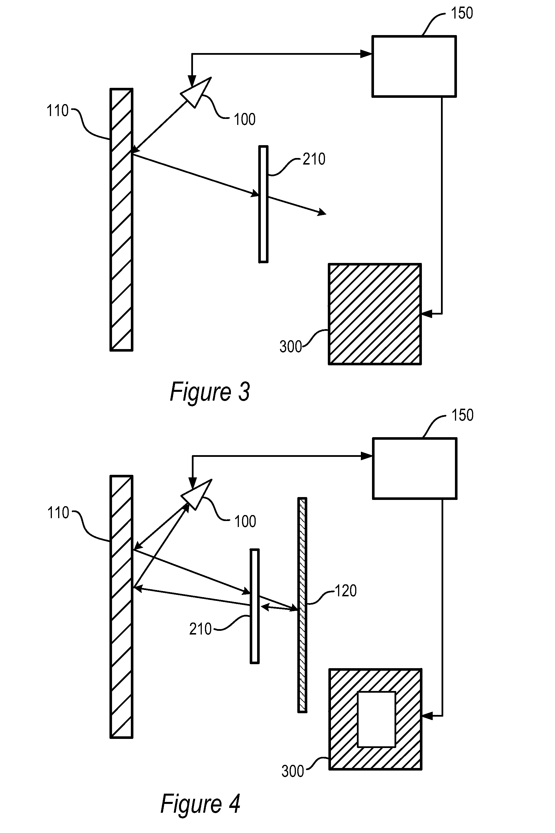
[0013]The term “microwave radiation” refers to the band of electromagnetic radiation having frequencies corresponding to about 1 GHz to about 1,000 GHz or wavelengths from 0.3 mm to 30 cm. Additionally, the term “microwave imaging system” refers to an imaging systems using microwave radiation for illumination of the subject.

[0014]A microwave imaging system is shown in FIG. 1. Such an imaging system is described in U.S. Pat. No. 6,965,340, entitled “System and Method for Security Inspection Using Microwave Imaging,” incorporated herein by reference.

[0015]In operation, source,receive antenna 100 illuminates programmable array panel 110. Processor 150 controls the individual elements of programmable array panel 110, and micro waves from source / receive antenna 100 to scan a particular voxel in three dimensional space, in particular, subject 200. While shown in FIG. 1 as coincident, source and receive antennas may be separate. If, as shown in Fig, 1, subject 200 is opaque, the image prod...


PUM


Abstract

Improved microwave imaging using a reflector. By providing a reflective surface in the range of the imaging system, additional information is available for imaging objects. The relative surface provides silhouette information on the object, and increases the effective thickness of the object to aid analysis.

Description

CROSS-REFERENCE TO RELATED APPLICATIONS[0001]This application is related by subject matter to U.S. application for patent Ser. No. 10 / 997,422, entitled “A Device for Reflecting Electromagnetic Radiation,” U.S. application for patent Ser. No. 10 / 997,583, entitled “Broadband Binary Phased Antenna,” both of which were fled on Nov. 24, 2004, and U.S. Pat. No. 6,965,340, entitled “System and Method for Security Inspection Using Microwave Imaging,” which issued on Nov. 15, 2005.[0002]This application is further related by subject matter to U.S. application for patent Ser. No. 11 / 088,536, entitled “System and Method for Efficient, High-Resolution Microwave Imaging Using Complementary Transmit and Receive Beam Patterns,” U.S. application for patent Ser. No. 11 / 088,831, entitled “System and Method for Inspecting Transportable Items Using Microwave Imaging,” U.S. application for patent Ser. No. 11 / 089,298, entitled “System and Method for Pattern Design in Microwave Programmable Arrays,” U.S. ...

Claims


Application Information

Patent Timeline
Patent Type & Authority Applications(United States)
IPC IPC(8): A61B5/05
CPCG01S13/89
Inventor WEEMS, WILLIAMTABER, ROBERT C.
Owner AGILENT TECH INC
Why Eureka
Try Eureka