High-pressure tank and method for fabricating the same

a technology of high-pressure tanks and tanks, which is applied in the direction of manufacturing tools, container filling under pressure, transportation and packaging, etc., can solve the problems of difficult application of techniques, difficult reinforcement, and limit the thickness of the dome section and the cylindrical gas discharge section to be increased, so as to achieve easy fabrication and increase the strength of the portion

Inactive Publication Date: 2006-11-21
SAM TECHOLOGY +2
View PDF1 Cites 5 Cited by
  • Summary
  • Abstract
  • Description
  • Claims
  • Application Information

AI Technical Summary

Benefits of technology

[0013]The present invention has been made in view of the foregoing points and therefore its object is to provide easily and inexpensively a high-pressure tank capable of fully withstanding high pressures of 35 to 75 MPa while keeping its lightness in weight.
[0016]With the above structure, in the invention of claim 1, the cylindrical gas discharge section and the neighboring dome section, likely to concentrate stress, can be increased in effective thickness by the thickness of the reinforcing collar, thereby obtaining sufficient strength in these sections. This provides a high-pressure tank strong enough to withstand high pressures of 35 to 75 MPa. Further, since the reinforcing collar is fitted not on the entire tank body but only on its part: the dome section and the cylindrical gas discharge section, this does not so much increase the weight of the entire high-pressure tank and maintains light weight, and provides facilitated fabrication and reduced cost.
[0018]With the above structure, in the invention of claim 2, the fitting of the boss of the reinforcing collar into the fitting recess of the dome section provides a firm engagement between the tank body and the reinforcing collar. Furthermore, the existence of the annular boss increases the thickness of that particular portion of the reinforcing collar and thereby increases the strength accordingly.
[0022]With the above structure, in the invention of claim 4, the tank body of an aluminum alloy is light in weight, which further reduces the tank weight as a whole.
[0024]With the above structure, in the invention of claim 5, the additional reinforcing collar need only be fitted onto the cylindrical gas discharge section of the tank body. Accordingly, a high-pressure tank having a light weight and capable of withstanding high pressures of 35 to 75 MPa can be fabricated easily without requiring much labor.
[0026]With the above structure, in the invention of claim 6, the additional reinforcing collar need only be fitted onto the cylindrical gas discharge section of the tank body to fit the boss in the fitting recess of the dome section. Accordingly, a high-pressure tank having a light weight and capable of fully withstanding high pressures of 35 to 75 MPa can be fabricated easily without requiring much labor. Furthermore, since the thickness of the portion of the reinforcing collar fitted with the fitting recess is increased, the strength of that portion is increased accordingly.

Problems solved by technology

However, the vicinity of the boundary between the dome section and the cylindrical gas discharge section is difficult to subject to winding and thus difficult to reinforce.
For the first-mentioned technique, however, there is a limit to how much the thickness of the dome section and the cylindrical gas discharge section can be increased because of the use of an elongated hollow cylindrical blank having a uniform thickness as a whole.
Therefore, this technique is difficult to apply particularly to high-pressure tanks for hydrogen gas into which the gas is charged at a pressure of between 35 MPa and 75 MPa.
In this case, however, the entire high-pressure tank thus fabricated will also be thickened and thereby increased in weight, which hinders weight reduction.
In addition, since the tank uses the thick elongated hollow cylindrical blank, its material cost will be high.
This Patent document 1 technique, however, requires the elongated hollow cylindrical blank to undergo two process steps of flow forming and spinning, which takes much labor.
This may invite the complete closure of the cylindrical gas discharge section and thereby necessitate subsequent boring of a gas outlet in a later process step, which requires extra labor.

Method used


Image

  • High-pressure tank and method for fabricating the same
  • High-pressure tank and method for fabricating the same
  • High-pressure tank and method for fabricating the same

Examples


embodiment 1

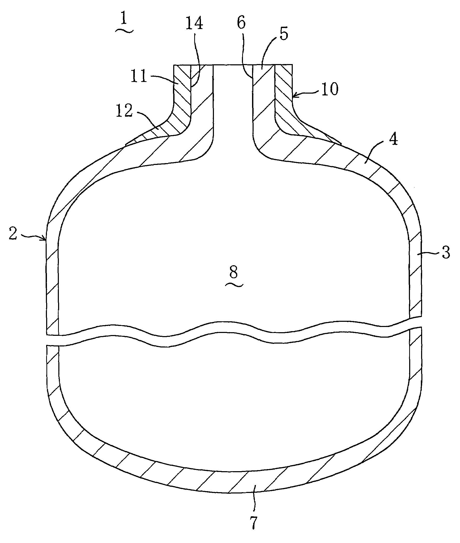
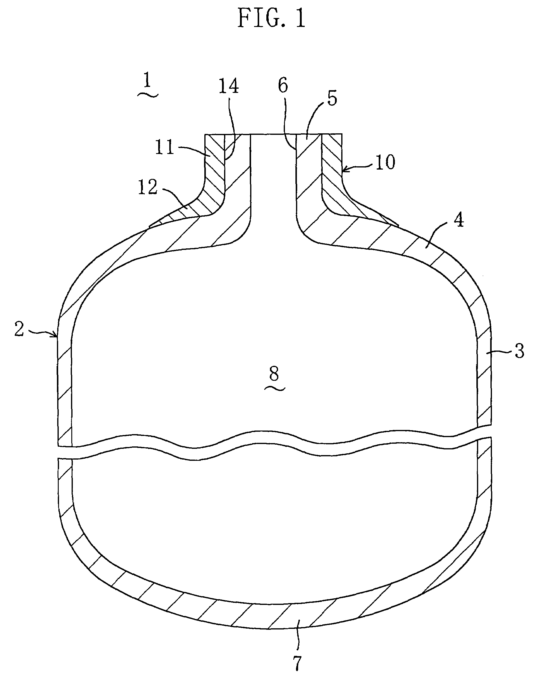
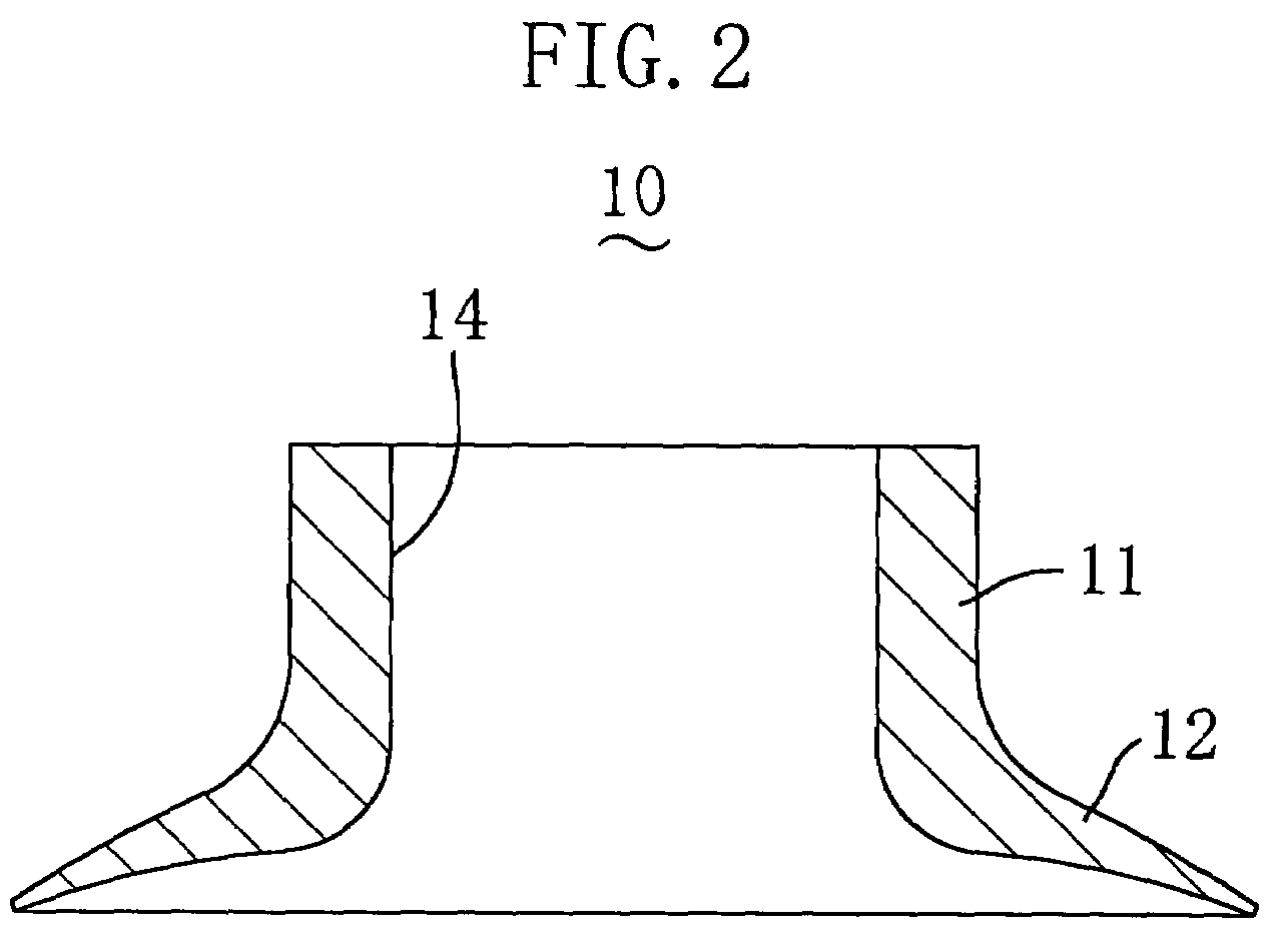
[0043]FIG. 1 shows a high-pressure tank 1 according to Embodiment 1 of the present invention. The high-pressure tank 1 includes a tank body 2 into which high-pressure gas, such as hydrogen gas, of 35 to 75 MPa is charged. The tank body 2 is formed so that a cylindrical gas discharge section 5 circular in cross section is protruded integrally from one end of a cylindrical middle section 3 circular in cross section through a dome section 4, the cylindrical gas discharge section 4 is formed with a gas outlet 6 and the cylindrical middle section 3 is integrally formed at the other end with a bottom section 7. The tank body 2 is provided internally with a hollow part 8 for containing high-pressure gas.

[0044]The tank body 2 is made of an aluminum alloy such as JIS A 6061 or JIS A 6062, formed by plastically deforming a hollow cylindrical blank and subjected to heat treatment such as T6 treatment after the forming. The dome section 4, the cylindrical gas discharge section 5 and the bottom ...

embodiment 2

[0055]FIG. 4 shows a high-pressure tank 1 according to Embodiment 2 of the present invention. The high-pressure tank 1 includes a tank body 2 into which high-pressure gas, such as hydrogen gas, of 35 to 75 MPa is charged. The tank body 2 is formed so that a cylindrical gas discharge section 5 circular in cross section is protruded integrally from one end of a cylindrical middle section 3 circular in cross section through a dome section 4, the cylindrical gas discharge section 4 is formed with a gas outlet 6 and the cylindrical middle section 3 is integrally formed at the other end with a bottom section 7. The tank body 2 is provided internally with a hollow part 8 for containing high-pressure gas.

[0056]The tank body 2 is made of an aluminum alloy such as JIS A 6061 or JIS A 6062, formed by plastically deforming a hollow cylindrical blank and subjected to heat treatment such as T6 treatment after the forming. The dome section 4, the cylindrical gas discharge section 5 and the bottom ...


PUM

PropertyMeasurementUnit
pressureaaaaaaaaaa
pressureaaaaaaaaaa
pressuresaaaaaaaaaa

Abstract

A cylindrical reinforcing collar is fitted onto a cylindrical gas discharge section of a tank body and then engaged integrally on the exterior of the tank body between the cylindrical gas discharge section and the dome section by shrink fitting. This provides, easily and inexpensively, a high-pressure tank capable of withstanding high pressures of 35 to 75 MPa while keeping its lightness in weight.

Description

CROSS-REFERENCE TO RELATED APPLICATIONS[0001]This application is a continuation-in-part application of U.S. patent application Ser. No. 10 / 307,495 filed on Dec. 2, 2002 now Pat. No. 6,908,006.BACKGROUND OF THE INVENTION[0002]1. Field of the Invention[0003]This invention relates to improvements of a high-pressure tank into which high-pressure gas is charged and improvements of a method for fabricating the same.[0004]2. Description of the Related Art[0005]High-pressure tanks into which a gas, such as natural gas or hydrogen gas, is charged and stored at high pressure, are generally subjected to winding which is a technique for wrapping carbon fibers or the like around the tank body for reinforcement. A cylindrical gas discharge section and a continuous dome section of the tank, in particular, are likely to concentrate stress and therefore must be reinforced firmly. However, the vicinity of the boundary between the dome section and the cylindrical gas discharge section is difficult to ...

Claims


Application Information

Patent Timeline
Patent Type & Authority Patents(United States)
IPC IPC(8): F17C1/02B23P11/02F17C5/00
CPCB23P11/02F17C5/00F17C2205/0305F17C2201/0109F17C2201/054Y10T29/49865F17C2203/0646F17C2203/0648F17C2209/224F17C2223/036F17C2260/011F17C2203/0617
Inventor SAKAGUCHI, TEPPEISAKAGUCHI, YOSHIKIHOGAN, SHAUN C.
Owner SAM TECHOLOGY
Why Eureka
Try Eureka