Convection Oven

a convection oven and oven technology, applied in the field of barbecue ovens, can solve the problems of difficult control of the heat generated by the burner without additional devices, and the cost of the burner is high

Active Publication Date: 2011-11-10
DAVID B KNIGHT & ASSOCS
View PDF14 Cites 35 Cited by
  • Summary
  • Abstract
  • Description
  • Claims
  • Application Information

AI Technical Summary

Problems solved by technology

These burners are costly and it may be difficult to control the heat generated with the burners without additional devices such as sophisticated logic thermometers, dampers, vents and / or baffles.

Method used


Image

  • Convection Oven
  • Convection Oven
  • Convection Oven

Examples


Embodiment Construction

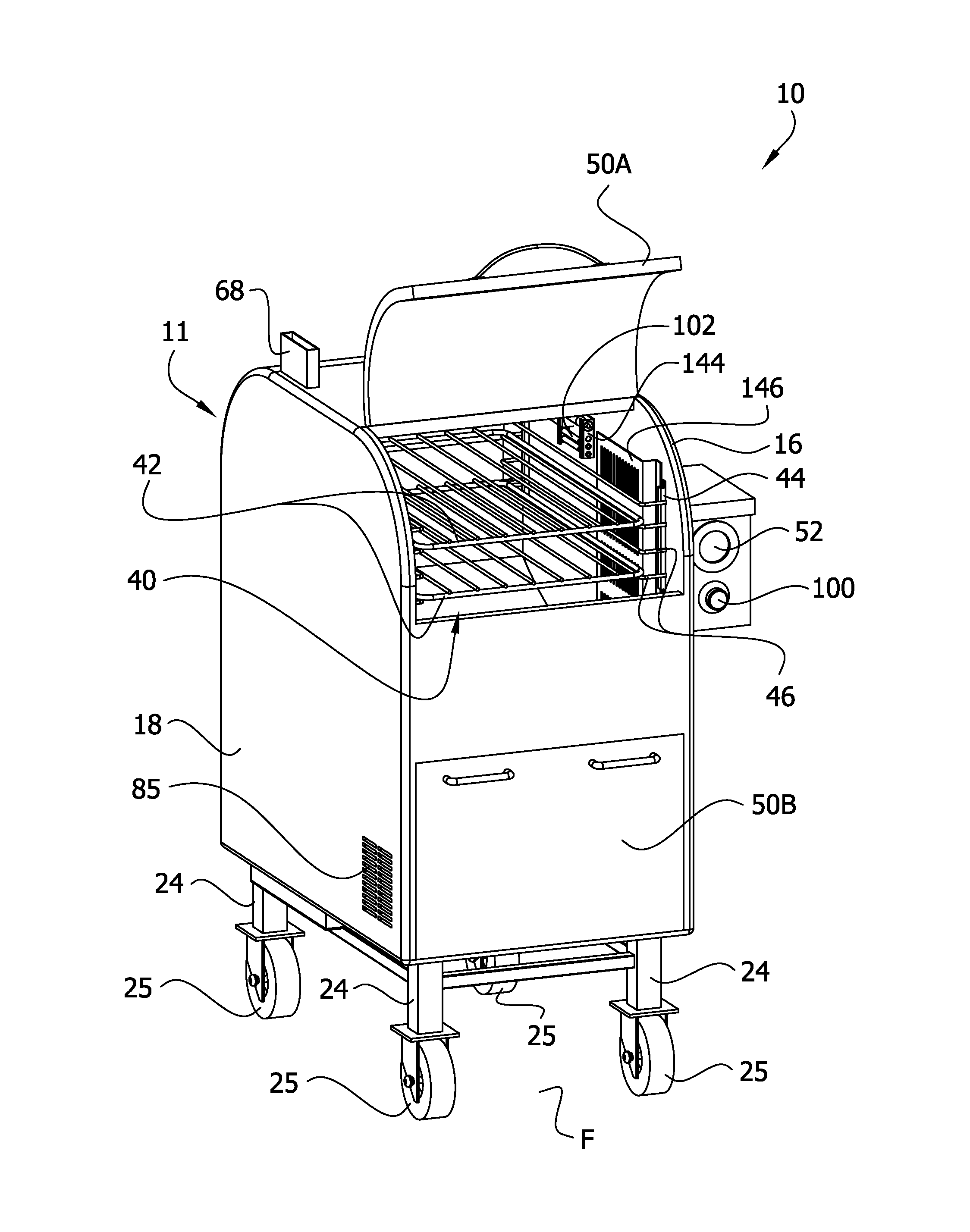
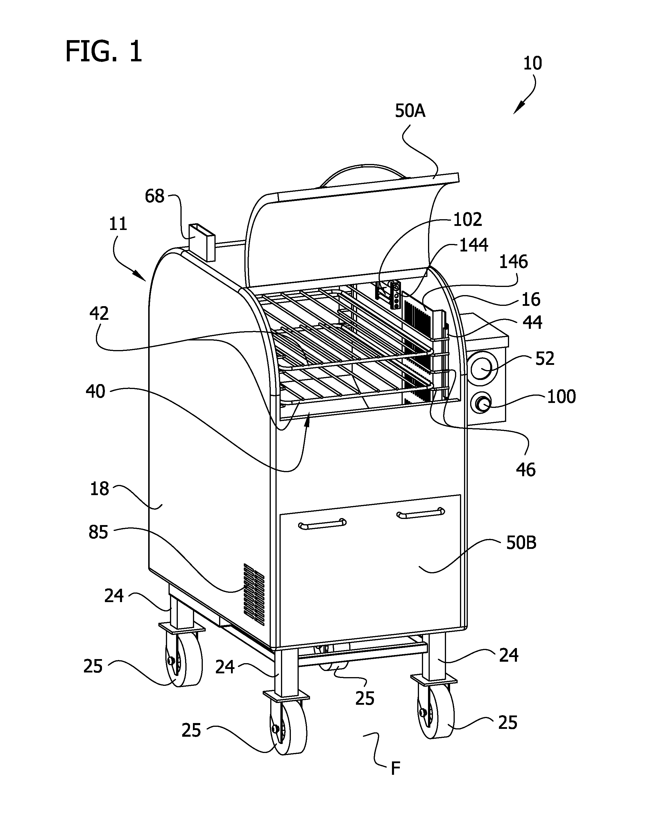
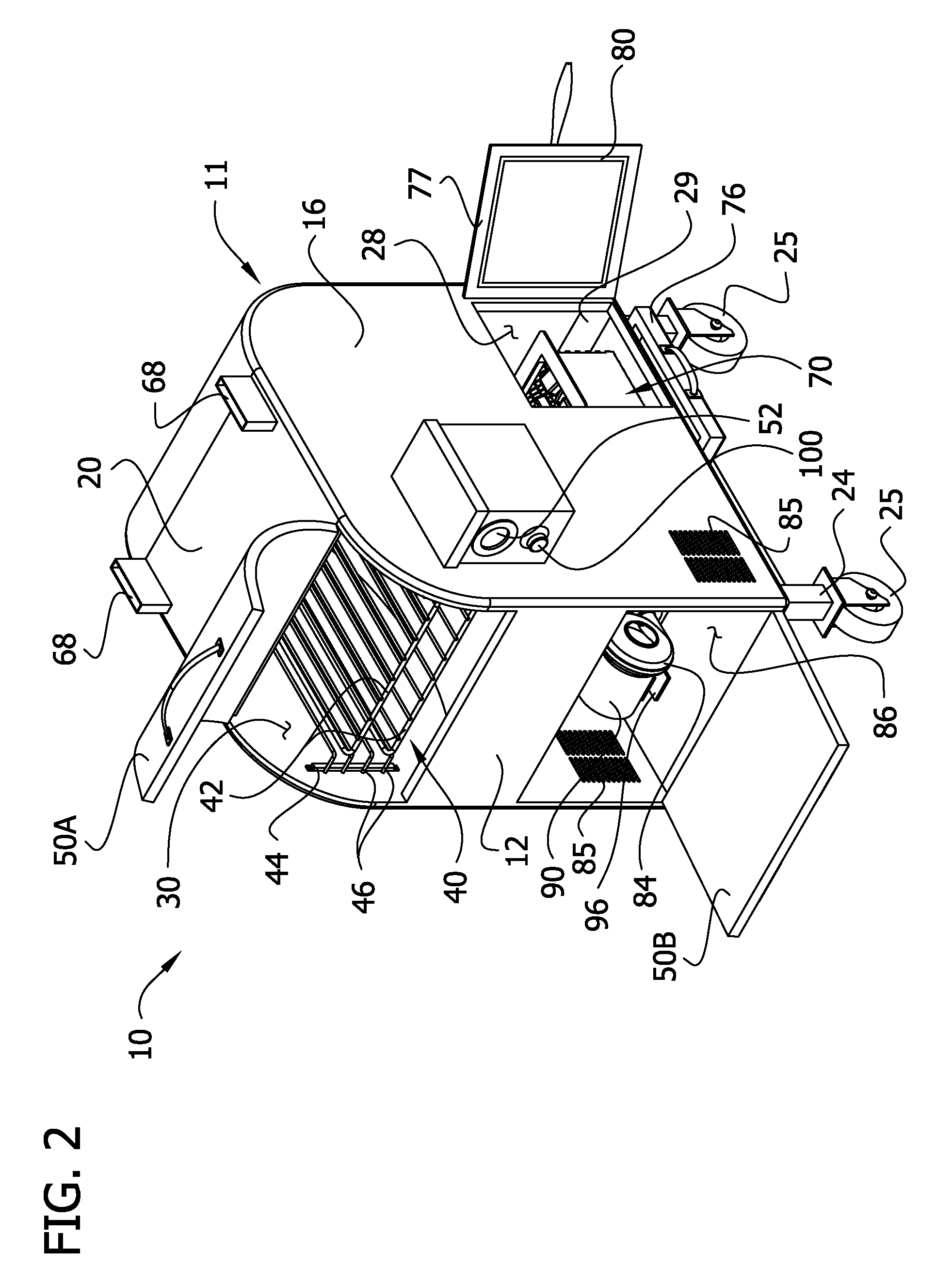
[0018]Referring now to the drawings and in particular to FIGS. 1-5, a barbecue oven that efficiently circulates heat and smoke around food in the oven is designated generally by reference numeral 10. For the purpose of illustration, the invention will be described in conjunction with a barbecue oven. The invention, however, should not be limited to this specific use, as it is instead intended that the invention be used in any application in which circulation of heated air around food is to be employed. The oven 10 includes a housing, indicated generally at 11 which comprises a front wall 12, back wall 14, side walls 16, 18, a top 20 and a bottom 22. The front, back and side walls 12, 14, 16, 18 define wall members which together form vertical walls of the housing 11. The walls 12, 14, 16, 18, top 20 and bottom 22 are preferably seam welded together to form the housing 11. The number of wall members forming the vertical wall may be other than described without departing from the scop...


PUM


Abstract

An oven for cooking foods includes a housing having a fire chamber and a cooking chamber disposed generally above the fire chamber. A vessel is receivable in the fire chamber and is adapted to hold combustible material therein to generate heat and smoke for cooking food in the cooking chamber. A blower is mounted on the housing. The blower is selectively operable to move air. A tube is attached to an outlet of the blower and extends into the fire chamber such that when the vessel is received in the fire chamber the tube extends to a position adjacent the vessel so that air from the blower is blown directly into the vessel without first passing a heating element. The oven does not require supplemental heat from a burner or similar heating element.

Description

FIELD OF THE INVENTION[0001]The present invention generally relates to barbecue ovens, and in particular to a barbecue oven having controlled heat and smoke flow.BACKGROUND OF THE INVENTION[0002]Barbecuing is a traditional cooking process that typically involves the cooking of foods by exposing them to relatively low temperature smoke for a number of hours. The structure used for barbecuing typically includes a heating or fire chamber, a cooking chamber and a conduit or flue through which smoke and heated combustion gases are transported from the fire chamber to the cooking chamber. Smoke and heat is produced by burning a smoke producing substance in the fire chamber such as wood. The wood is burned using a heating element such as a gas or electric burner. These burners are costly and it may be difficult to control the heat generated with the burners without additional devices such as sophisticated logic thermometers, dampers, vents and / or baffles. Accordingly, there exists a need f...

Claims


Application Information

Patent Timeline
Patent Type & Authority Applications(United States)
IPC IPC(8): F24C15/00
CPCA47J37/0754F24B5/021F24B1/202Y02A40/928
Inventor KNIGHT, DAVID B.
Owner DAVID B KNIGHT & ASSOCS
Why Eureka
Try Eureka