
Apparatus and Method for Dynamic Resolution of Secondary Communication System Resources

a communication system and dynamic resolution technology, applied in the field of communication systems, can solve problems such as the decrease of the used carrier bandwidth of the base station

Inactive Publication Date: 2011-11-10
NOKIA TECHNOLOGLES OY
View PDF8 Cites 54 Cited by
  • Summary
  • Abstract
  • Description
  • Claims
  • Application Information

AI Technical Summary

Benefits of technology

[0013]The foregoing has outlined rather broadly the features and technical advantages of the present invention in order that the detailed description of the invention that follows may be better understood. Additional features and advantages of the invention will be described hereinafter, which form the subject of the claims of the invention. It should be appreciated by those skilled in the art that the conception and specific embodiment disclosed may be readily utilized as a basis for modifying or designing other structures or processes for carrying out the same purposes of the present invention. It should also be realized by those skilled in the art that such equivalent constructions do not depart from the spirit and scope of the invention as set forth in the appended claims.

Problems solved by technology

Integrating device-to-device or machine-to-machine communication into a cellular communication system introduces a number of challenges.
One of the more problematic issues is how to perform communication system resource allocation among devices from the pool of primary communication system resources.
In the case where the load in a cell due to cellular communication mode devices is lower than the current bandwidth allocation that would be provided for the carrier, the base station may decrease the used carrier bandwidth.
An unsolved problem is how a base station assigns and signals such secondary communication system resources that are not within the effective bandwidth, but within the maximum allowed bandwidth of the primary communication system.
Another problem is how to use the same communication system resource allocation signaling in the cell when the ratio of used and unused bandwidth of the primary communication system changes.

Method used


Image

  • Apparatus and Method for Dynamic Resolution of Secondary Communication System Resources
  • Apparatus and Method for Dynamic Resolution of Secondary Communication System Resources
  • Apparatus and Method for Dynamic Resolution of Secondary Communication System Resources

Examples


Embodiment Construction

[0024]The making and using of the presently preferred embodiments are discussed in detail below. It should be appreciated, however, that the present invention provides many applicable inventive concepts that can be embodied in a wide variety of specific contexts. The specific embodiments discussed are merely illustrative of specific ways to make and use the invention, and do not limit the scope of the invention. In view of the foregoing, the present invention will be described with respect to exemplary embodiments in a specific context of an apparatus, method and system for dynamic resolution of secondary communication system resources for communications in a communication system. The apparatus, method and system are applicable, without limitation, to any communication system including existing and future 3GPP technologies (i.e., UMTS, LTE, and its future variants such as 4th generation (“4G”) communication systems).

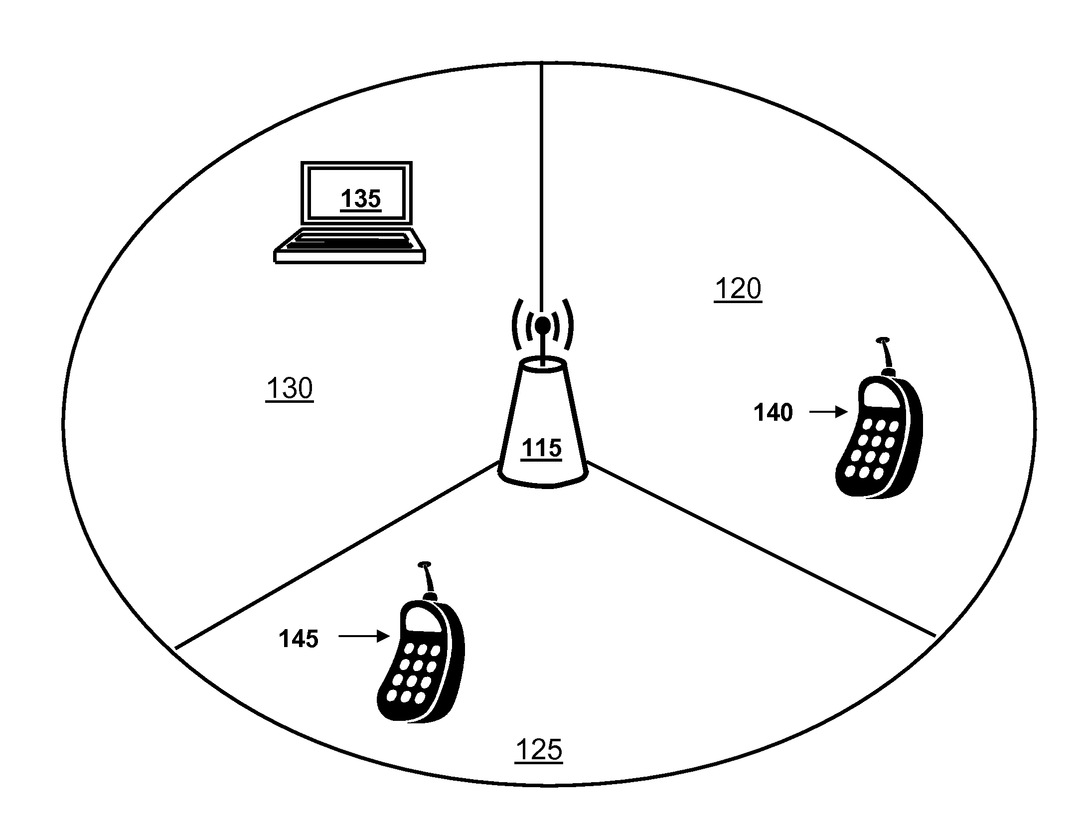
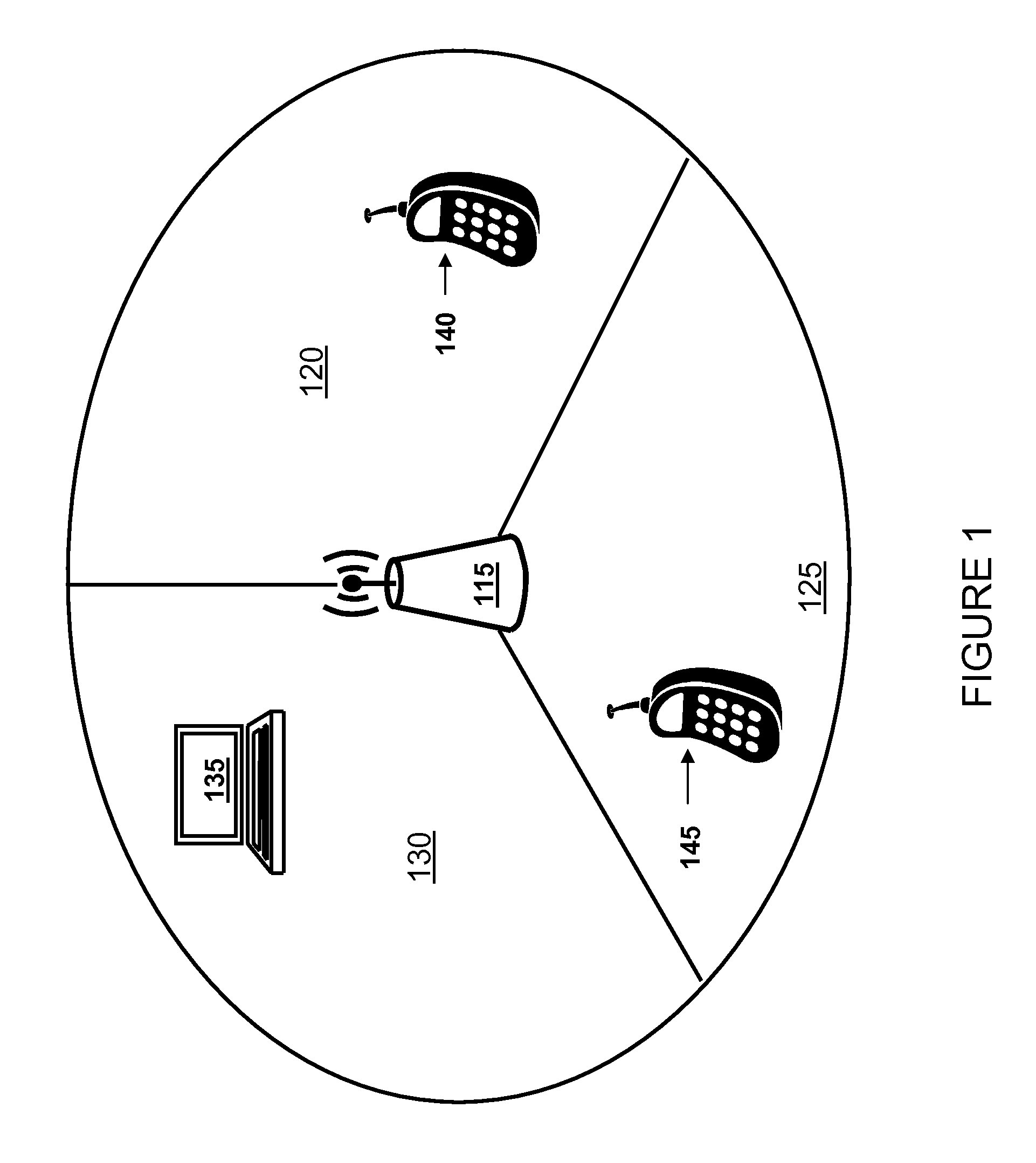
[0025]Turning now to FIG. 1, illustrated is a system level diagram ...


PUM


Abstract

An apparatus, method and system for dynamic resolution of secondary communication system resources for communications in a communication system. In one embodiment, an apparatus includes a processor and memory including computer program code. The memory and the computer program code are configured to, with the processor, cause the apparatus to receive an allocation of secondary communication system resources on a control channel of a primary communication system to enable communication in a secondary communication system. The secondary communication system resources are a function of unused primary communication system resources in the primary communication system.

Description

TECHNICAL FIELD[0001]The present invention is directed, in general, to communication systems and, in particular, to an apparatus, method and system for dynamic resolution of secondary communication system resources for communications in a communication system.BACKGROUND[0002]Long term evolution (“LTE”) of the Third Generation Partnership Project (“3GPP”), also referred to as 3GPP LTE, refers to research and development involving the 3GPP LTE Release 8 and beyond, which is the name generally used to describe an ongoing effort across the industry aimed at identifying technologies and capabilities that can improve systems such as the universal mobile telecommunication system (“UMTS”). The notation “LTE-A” is generally used in the industry to refer to further advancements in LTE. The goals of this broadly based project include improving communication efficiency, lowering costs, improving services, making use of new spectrum opportunities, and achieving better integration with other open...

Claims


Application Information

Patent Timeline
IPC IPC(8): H04W72/04
CPCH04W72/042H04L5/0091H04L5/0037H04W16/14H04W72/52H04W72/23H04W28/16H04W72/04
Inventor HAKOLA, SAMI-JUKKAKOSKELA, TIMO K.PIKKARAINEN, MATTI
Owner NOKIA TECHNOLOGLES OY
Learn More