
Apparatus and method for monitoring a computer system

a computer system and apparatus technology, applied in the field of monitoring computer systems, can solve the problems of difficult problem diagnosis, difficult to obtain historical diagnostic information, and inability to expect frequent manual intervention by administrators on long running or complex systems, and achieve the effect of lessening the impact of performance/storag

Active Publication Date: 2011-11-10
IBM CORP
View PDF15 Cites 19 Cited by
  • Summary
  • Abstract
  • Description
  • Claims
  • Application Information

AI Technical Summary

Benefits of technology

[0024]Preferred embodiments of the present invention thus advantageously provide an automated apparatus and method for causing the provision of appropriate historical diagnostic data when an operator alert is driven.
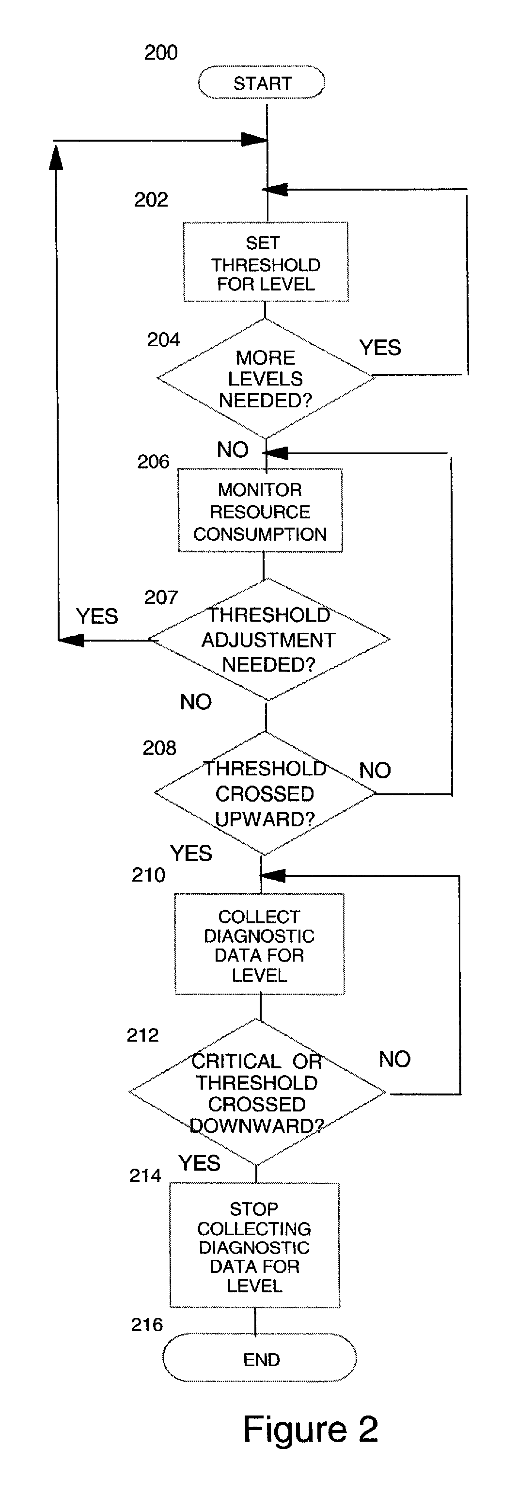
[0025]In embodiments of the present invention, there is provided an automated system for providing historical diagnostic information when an operator alert is driven. A predetermined threshold between an average level for a resource and a critical point is set, and when this threshold is reached the application automatically activates its diagnostic collection facility, leaving collection active until the monitored resource drops below the threshold for collection. If a failure alert is driven, there will be diagnostic information from the initial time that the monitored resource hit the diagnostic threshold through to the point of failure for offline analysis. By only triggering the diagnostic collection when a problem may be imminent, the performance / storage impact is lessened.

Problems solved by technology

1. It is impractical to expect frequent manual intervention by an administrator on long running or complex systems.
Therefore alerts are not driven frequently and are typically only driven when a critical system failure occurs.
When an alert is triggered there is frequently very little historical diagnostic information available.
This leads to the following problems:
1. A lack of historical diagnostic data makes problem diagnosis difficult, so the operator does not know what actions to take to resolve the problem.
2. The systems administrator tends to react to problems after they occur rather than identify potential problems in advance.

Method used


Image

  • Apparatus and method for monitoring a computer system
  • Apparatus and method for monitoring a computer system
  • Apparatus and method for monitoring a computer system

Examples


Embodiment Construction

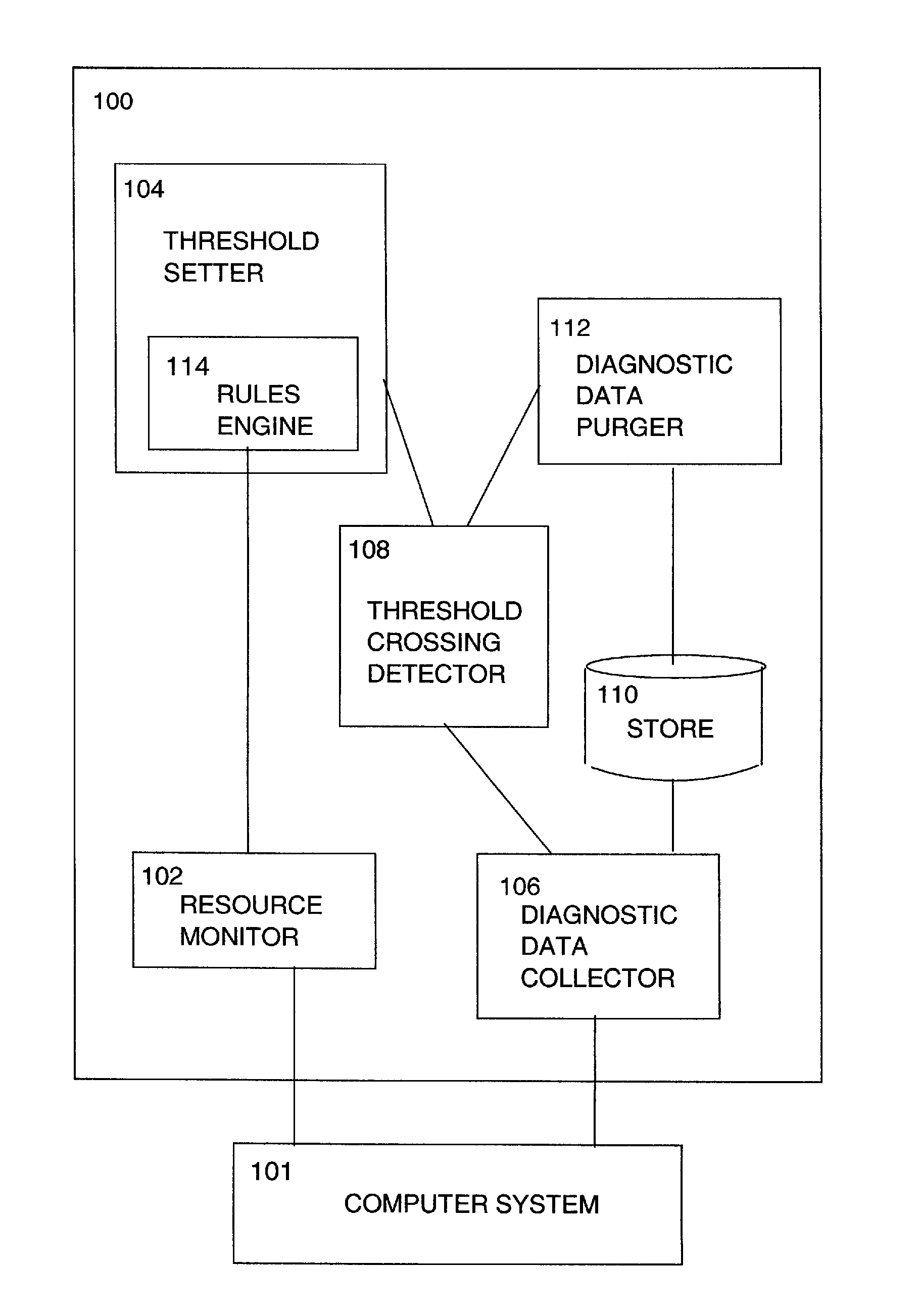
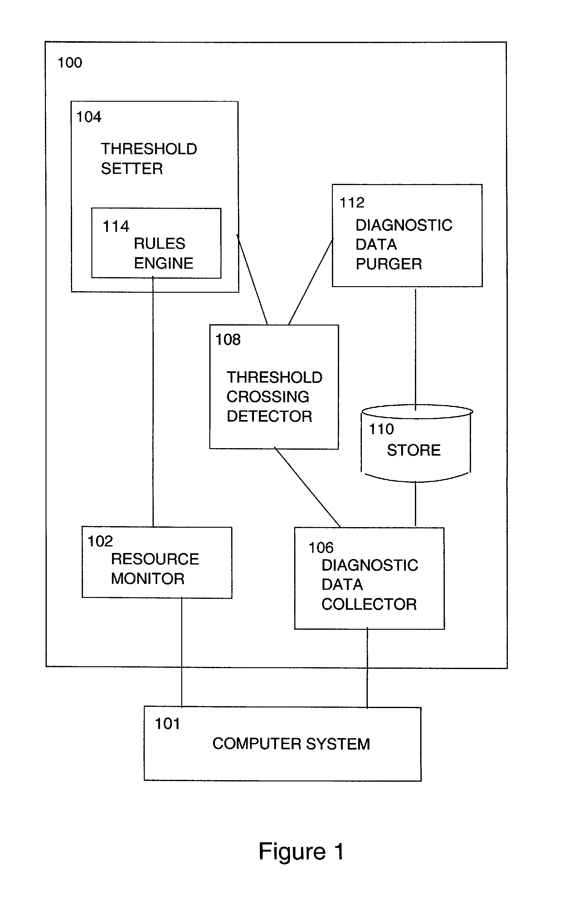
[0030]Referring now to FIG. 1, there is shown an apparatus 100 for monitoring a computer system 101, typically one having a facility for alerting an operator to failures associated with critical resource consumption. Apparatus 100 comprises a resource monitoring component 102 for monitoring resource consumption and a threshold setting component 104 for setting a threshold of resource consumption between an average resource consumption value and a critical resource consumption value. Apparatus 100 further comprises a diagnostic data collection component 106 and a threshold crossing detection component 108. Diagnostic data collection component 106 is operable, in response to threshold crossing detection component 108 detecting a threshold crossing from a lower resource consumption value to a higher resource consumption value, to start diagnostic data collection.

[0031]Additionally, diagnostic data collection component 106 is operable, in response to threshold crossing detection compone...


PUM


Abstract

An apparatus and method for monitoring a computer system operable for alerting an operator to failures associated with critical resource consumption and comprises: a resource monitoring component for monitoring resource consumption; a threshold setting component for setting a threshold of resource consumption between an average resource consumption value and a critical resource consumption value; a diagnostic data collection component; and a threshold crossing detection component; wherein the diagnostic data collection component is operable, in response to the threshold crossing detection component detecting a threshold crossing, to start or stop diagnostic data collection.

Description

FIELD OF THE INVENTION[0001]The present invention relates to the field of monitoring computer systems and more specifically to an automated apparatus and method for causing the provision of appropriate historical diagnostic data when an operator alert is driven.BACKGROUND OF THE INVENTION[0002]Monitoring applications can be configured to alert an end-user when a certain monitored resource exceeds or drops below a pre-defined threshold. These thresholds are typically determined by observing the use of the system for a period of time. The implications of this approach are:[0003]1. It is impractical to expect frequent manual intervention by an administrator on long running or complex systems. Therefore alerts are not driven frequently and are typically only driven when a critical system failure occurs.[0004]2. Due to performance or storage constraints the gathering of diagnostic information does not occur continually. When an alert is triggered there is frequently very little historica...

Claims


Application Information

Patent Timeline
Patent Type & Authority Applications(United States)
IPC IPC(8): G06F11/30
CPCG06F11/076G06F11/3093G06F11/0778
Inventor FRESSON, PAULKNIGHTS, SIMON P.WILSON, RUSSELL
Owner IBM CORP
Learn More