
Assembly of multi-chip modules using reflowable features

Active Publication Date: 2011-11-17
ORACLE INT CORP
View PDF6 Cites 14 Cited by
  • Summary
  • Abstract
  • Description
  • Claims
  • Application Information

AI Technical Summary

Benefits of technology

[0012]In some embodiments, the reflow characteristic of a given second positive feature in the set of second positive features varies as a function of an angular position on a surface of the given second positive feature. This angular variation of the reflow characteristic of the given second positive feature may facilitate modification of a spacing between the first substrate and the second substrate.
[0015]In some embodiments, a set of first proximity connectors are disposed on one of the first surface and the second surface, and a set of second proximity connectors are disposed on the third surface. The set of second coupling elements may align the first proximity connectors and the second proximity connectors, and may assemble the MCM, thereby facilitating proximity communication between the first substrate and the second substrate.
[0016]Furthermore, the first reflow characteristic and the second reflow characteristic may facilitate selective disassembly of the MCM during rework.
[0018]Note that the flexible connector may be incompatible with the first peak temperature, and the second peak temperature, which is less than the first peak temperature, may therefore facilitate assembly of the chip package.

Problems solved by technology

As integrated-circuit (IC) technology continues to scale to smaller critical dimensions, it is increasingly difficult for existing interconnects to provide suitable communication characteristics, such as: high bandwidth, low power, reliability and low cost.
However, it is difficult to bond chips to each other and to carriers (such as printed circuit boards) in chip stacks using existing assembly techniques because of stringent requirements for alignment accuracy and manufacturing throughput.
While this existing assembly technique can provide high alignment accuracy among the chips in the MCM, it typically involves multiple assembly operations, which makes assembly of the MCM complicated, time-consuming and expensive.

Method used


Image

  • Assembly of multi-chip modules using reflowable features
  • Assembly of multi-chip modules using reflowable features
  • Assembly of multi-chip modules using reflowable features

Examples


Embodiment Construction

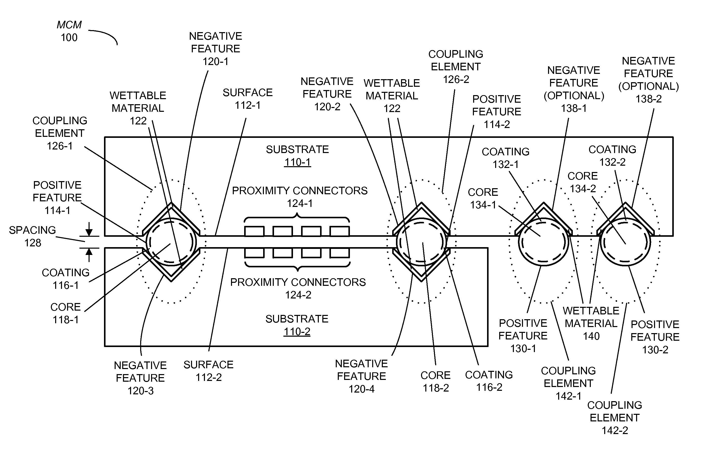
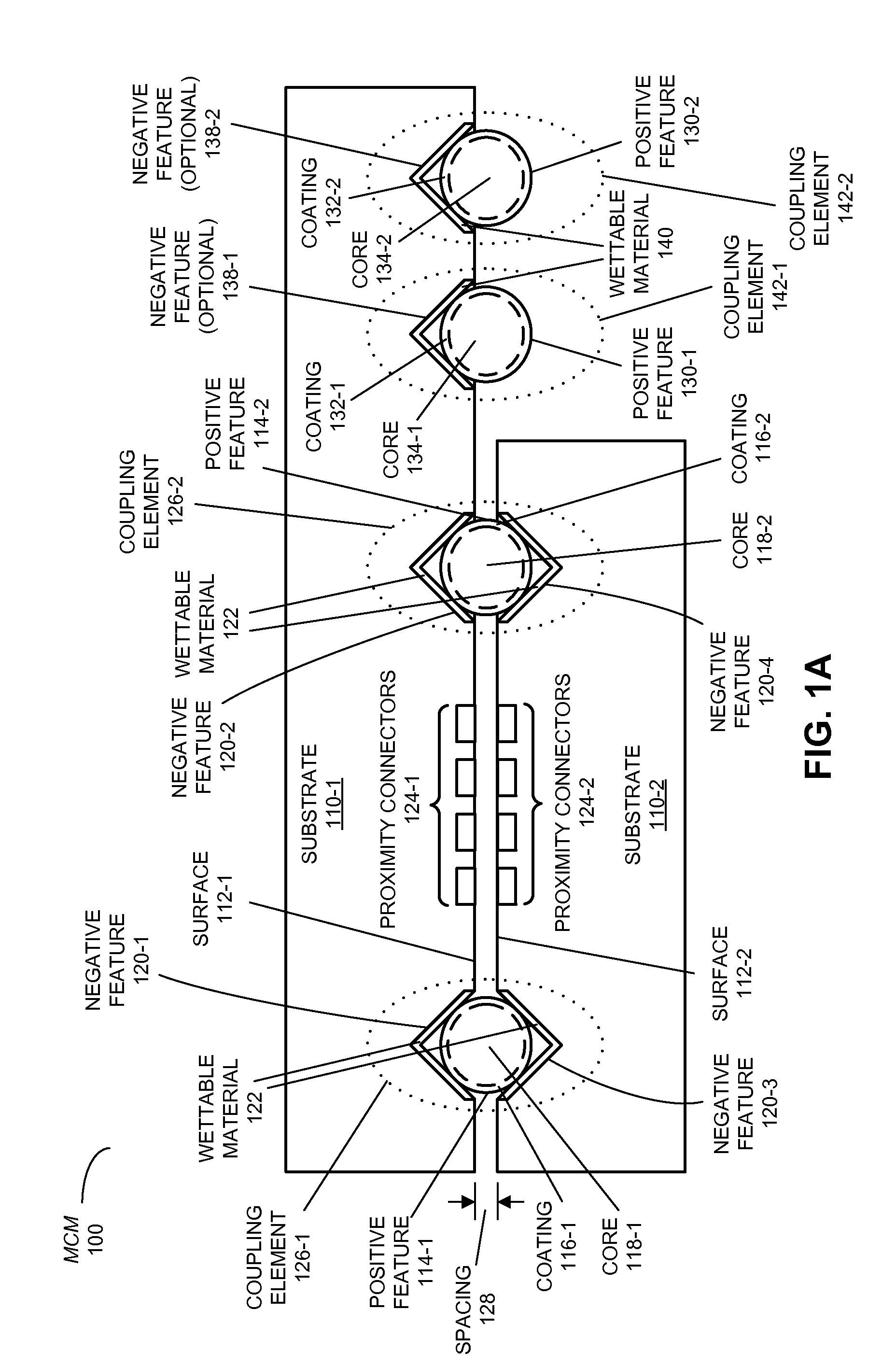
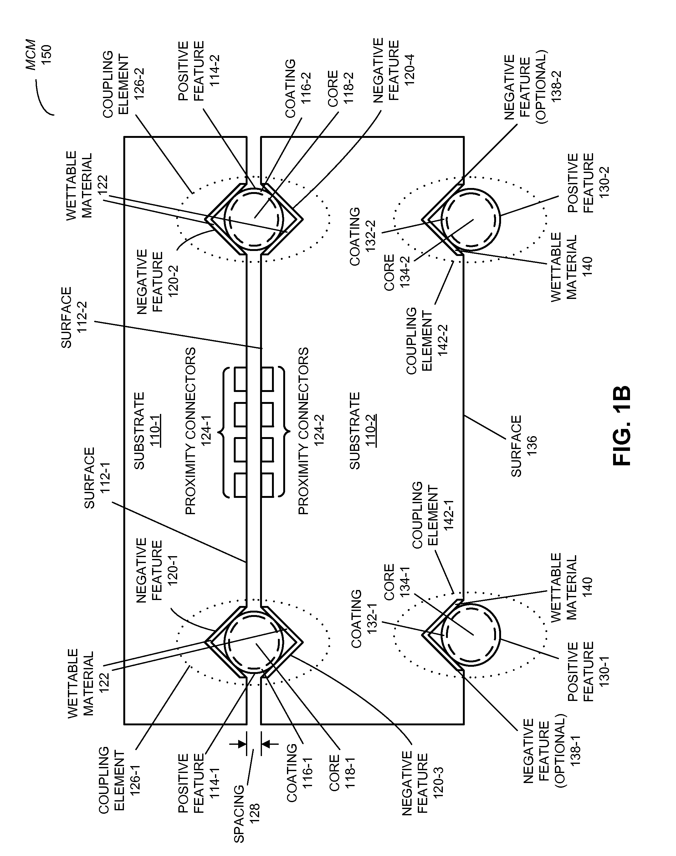
[0033]Embodiments of a multi-chip module (MCM), a package, an electronic device that includes the MCM or the package, and a technique for assembling the MCM are described. This MCM includes at least two substrates, having facing surfaces, which are mechanically coupled by a set of coupling elements having a reflow characteristic. In addition, one of the two substrates includes another set of coupling elements having another reflow characteristic, which is different than the reflow characteristic. These different reflow characteristics of the sets of coupling elements allow different temperature profiles to be used when bonding the two substrates to each other than when bonding the one of the two substrates to a carrier. For example, the temperature profiles may have different peak temperatures and / or different durations from one another.

[0034]These reflow characteristics may facilitate the integration of multiple chips in the MCM. In particular, relative to existing assembly techniq...


PUM


Abstract

A multi-chip module (MCM) that includes at least two substrates, having facing surfaces, which are mechanically coupled by a set of coupling elements having a reflow characteristic, is described. One of the two substrates includes another set of coupling elements having another reflow characteristic, which is different than the reflow characteristic. These different reflow characteristics of the sets of coupling elements allow different temperature profiles to be used when bonding the two substrates to each other than when bonding the one of the two substrates to a carrier. For example, the temperature profiles may have different peak temperatures and / or different durations from one another. These reflow characteristics may facilitate low-cost, high-yield assembly and alignment of the substrates in the MCM, and may allow temperature-sensitive components to be included in the MCM.

Description

BACKGROUND[0001]1. Field[0002]The present disclosure generally relates to multi-chip modules (MCMs) for semiconductor chips. More specifically, the present disclosure relates to an MCM that includes assembly features with different reflow characteristics that are reflowed during assembly of the MCM.[0003]2. Related Art[0004]As integrated-circuit (IC) technology continues to scale to smaller critical dimensions, it is increasingly difficult for existing interconnects to provide suitable communication characteristics, such as: high bandwidth, low power, reliability and low cost. Engineers and researchers are investigating chip stacking in multi-chip modules (MCMs) to address these problems, and to enable future high-density, high-performance systems.[0005]However, it is difficult to bond chips to each other and to carriers (such as printed circuit boards) in chip stacks using existing assembly techniques because of stringent requirements for alignment accuracy and manufacturing throug...

Claims


Application Information

Patent Timeline
IPC IPC(8): H01L23/498H01L21/60
CPCH01L23/13H01L2924/0002H01L23/49811H01L25/0652H01L25/50H01L2225/06531H01L2225/06593H01L2924/09701H01L24/14H01L2224/16147H01L2224/17517H01L2224/13561H01L2224/13541H01L2224/13578H01L24/13H01L24/16H01L24/17H01L24/81H01L2224/0401H01L2224/05557H01L2224/05558H01L2224/05571H01L2224/05655H01L2224/05671H01L2224/13147H01L2224/13155H01L2224/1319H01L2224/1357H01L2224/13611H01L2224/14051H01L2224/14505H01L2224/14517H01L2224/16227H01L2224/1703H01L2224/81815H01L2924/15153H01L2224/81211H01L2224/81141H01L2224/16225H01L23/48H01L2924/00012H01L2924/00014H01L2924/01082H01L2924/01079H01L2924/01029H01L2924/01049H01L2924/206H01L2924/01028H01L2224/05552H01L2924/15787H01L2924/14H01L2924/00
Inventor THACKER, HIREN D.SHI, JINGCUNNINGHAM, JOHN E.KRISHNAMOORTHY, ASHOK V.
Owner ORACLE INT CORP
Learn More