
Method And System For Measuring And Compensating For Process Direction Artifacts In An Optical Imaging System In An Inkjet Printer

an optical imaging system and inkjet printer technology, applied in the field of printhead alignment, can solve the problems of inability to analyze the printed image in situ, inability to generate a picture of the printed image, and inability to produce inaccuracy in the image data generated by the optical imaging system

Active Publication Date: 2011-11-17
XEROX CORP
View PDF0 Cites 6 Cited by
  • Summary
  • Abstract
  • Description
  • Claims
  • Application Information

AI Technical Summary

Benefits of technology

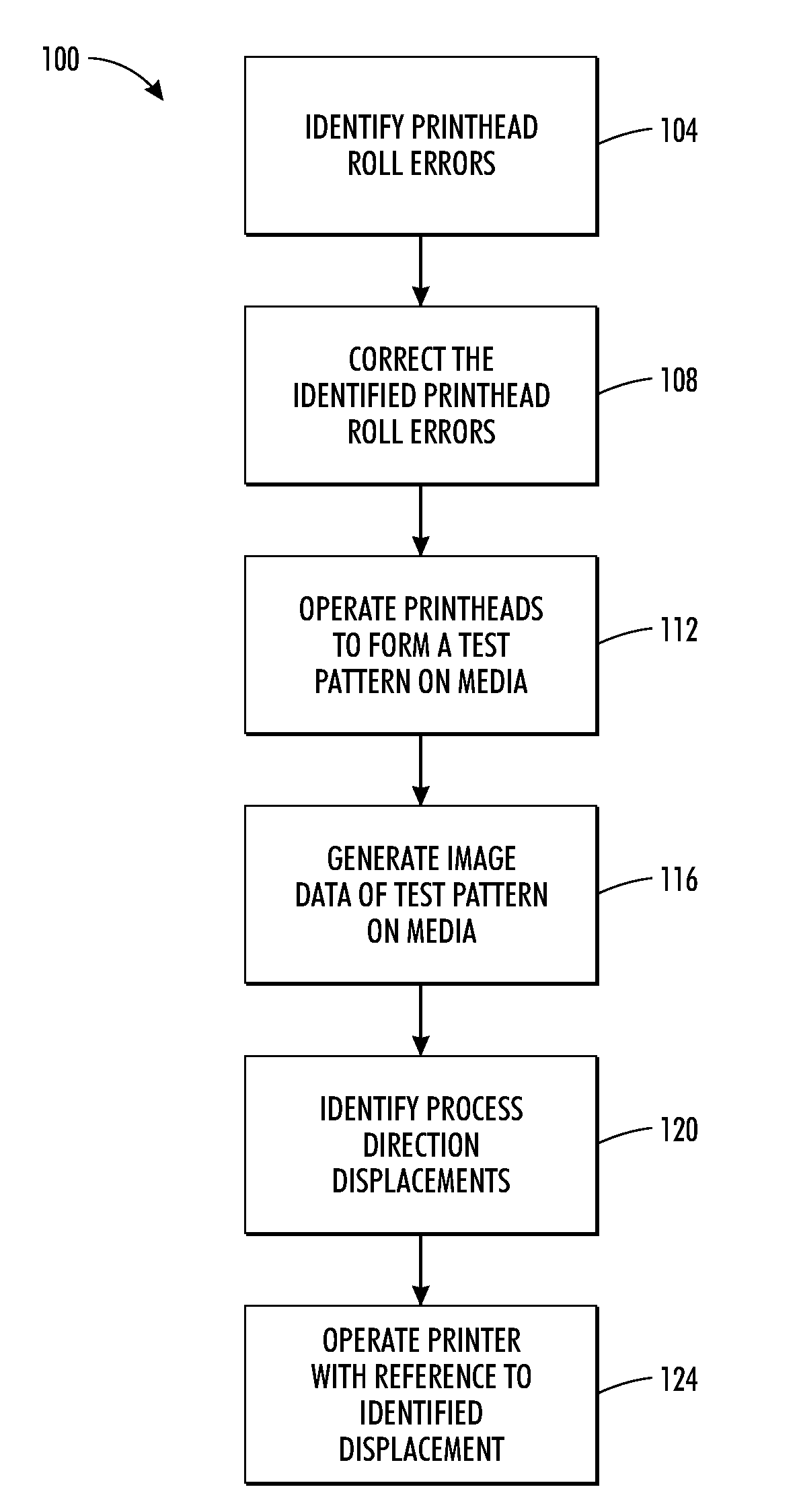
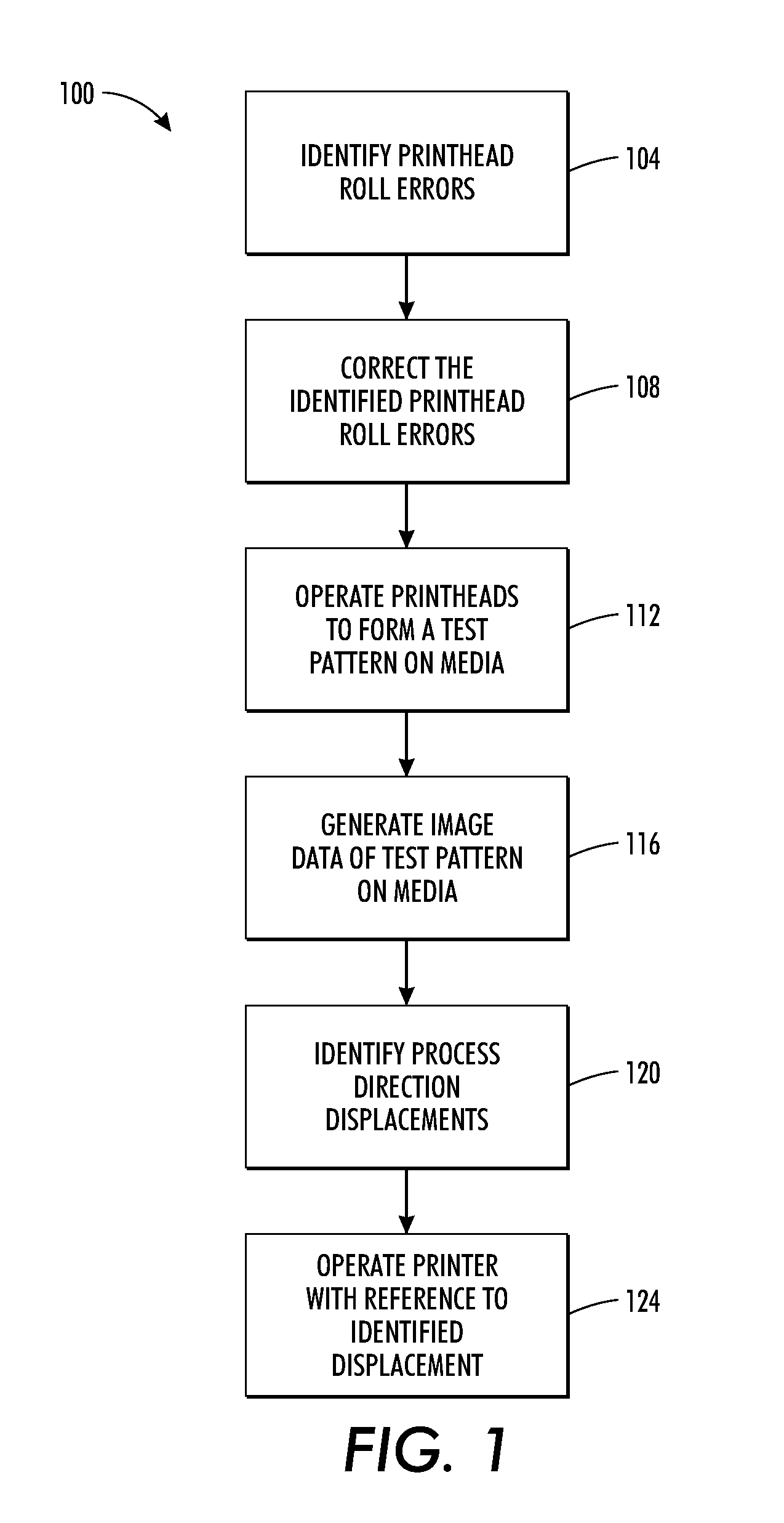
[0009]A method of operating a printer enables skew, bow, and lens artifacts in image data to be detected and compensation techniques enabled. The method includes identifying a printhead roll error for each printhead in a plurality of printheads in a printer, moving each printhead by an amount that corrects the printhead roll error for the corresponding printhead, generating a plurality of dashes on media with the plurality of printheads as the media moves past the plurality of printheads, identifying a position for each dash in the process direction from image data of the plurality of dashes on the media, identifying a displacement in the process direction for each optical detector in a linear array of optical detectors used to generated the image data of the plurality of dashes, the displacement being identified with reference to the identified positions for the dashes, and operating the printer to compensate for the identified displacements of the optical detectors.

Problems solved by technology

This method of generating a picture of the printed image suffers from the inability to analyze the printed image in situ and from the inaccuracies imposed by the external scanner.
Arranging the optical sensors on a linear array may produce inaccuracies in the image data generated by the optical imaging system.
Another inaccuracy may arise if the linear array is not truly straight.
Another issue that may arise with the linear array of optical detectors is the orientation of the lenses that directed reflected light onto the optical detectors.

Method used


Image

  • Method And System For Measuring And Compensating For Process Direction Artifacts In An Optical Imaging System In An Inkjet Printer
  • Method And System For Measuring And Compensating For Process Direction Artifacts In An Optical Imaging System In An Inkjet Printer
  • Method And System For Measuring And Compensating For Process Direction Artifacts In An Optical Imaging System In An Inkjet Printer

Examples


Embodiment Construction

[0023]Referring to FIG. 6, an inkjet imaging system 5 is shown that has been configured to enable electrical motors used to align printheads to be calibrated with reference to the sensitivity and backlash of the motors. For the purposes of this disclosure, the imaging apparatus is in the form of an inkjet printer that employs one or more inkjet printheads and an associated solid ink supply. However, the motor calibration methods described herein are applicable to any of a variety of other imaging apparatuses that use electromechanical motors or other actuators to align the positions of printheads in the system.

[0024]The imaging system includes a print engine to process the image data before generating the control signals for the inkjet ejectors for ejecting colorants. Colorants may be ink, or any suitable substance that includes one or more dyes or pigments and that may be applied to the selected media. The colorant may be black, or any other desired color, and a given imaging appar...


PUM


Abstract

A printer operating method enables a controller to identify process direction errors in an optical imaging system. The method includes identifying a printhead roll error for each printhead in a plurality of printheads in a printer, moving each printhead by an amount that corrects the printhead roll error for the corresponding printhead, generating a plurality of dashes on media with the plurality of printheads as the media moves past the plurality of printheads, identifying a position for each dash in the process direction from image data of the plurality of dashes on the media, identifying a displacement in the process direction for each optical detector in a linear array of optical detectors used to generated the image data of the plurality of dashes, the displacement being identified with reference to the identified positions for the dashes, and operating the printer to compensate for the identified displacements of the optical detectors.

Description

TECHNICAL FIELD [0001]This disclosure relates generally to printhead alignment in an inkjet printer having one or more printheads, and, more particularly, to an optical imaging system used to generate image data of test patterns used to align the printheads in an inkjet printer.BACKGROUND [0002]Ink jet printers have printheads that operate a plurality of inkjets that eject liquid ink onto an image receiving member. The ink may be stored in reservoirs located within cartridges installed in the printer. Such ink may be aqueous ink or an ink emulsion. Other inkjet printers receive ink in a solid form and then melt the solid ink to generate liquid ink for ejection onto the imaging member. In these solid ink printers, the solid ink may be in the form of pellets, ink sticks, granules or other shapes. The solid ink pellets or ink sticks are typically placed in an ink loader and delivered through a feed chute or channel to a melting device that melts the ink. The melted ink is then collecte...

Claims


Application Information

Patent Timeline
Patent Type & Authority Applications(United States)
IPC IPC(8): B41J29/38
CPCB41J3/543B41J2029/3935B41J29/393
Inventor MIZES, HOWARD A.SHIN, HELEN HAEKYUNGZHANG, YEQING
Owner XEROX CORP
Learn More