
Methods for Target Tracking, Classification and Identification by Using Foveal Sensors

a technology of target tracking and classification, applied in the field of target tracking, classification and identification by using foveal sensors, can solve the problems of low energy captured by each sensor-cell, multiple objects being captured in the same pixel, and becoming difficult to identify

Inactive Publication Date: 2011-11-17
LI LE +8
View PDF4 Cites 48 Cited by
  • Summary
  • Abstract
  • Description
  • Claims
  • Application Information

AI Technical Summary

Benefits of technology

[0029]A method for operating a sensor system may include the steps of performing a scan over a first predetermined area with at least a low or a moderate spatial resolution. performing a classification over the image frame data; finding a target having a material which matches a predetermined material, performing a foveated spatial scan to reimage the area with the highest spatial resolution.

Problems solved by technology

If the pixels are too large, then multiple objects are captured in the same pixel and become difficult to identify.
If the pixels are too small, then the energy captured by each sensor-cell is low, and the decreased signal-to-noise ratio reduces the reliability of measured features.

Method used


Image

  • Methods for Target Tracking, Classification and Identification by Using Foveal Sensors
  • Methods for Target Tracking, Classification and Identification by Using Foveal Sensors
  • Methods for Target Tracking, Classification and Identification by Using Foveal Sensors

Examples


first embodiment

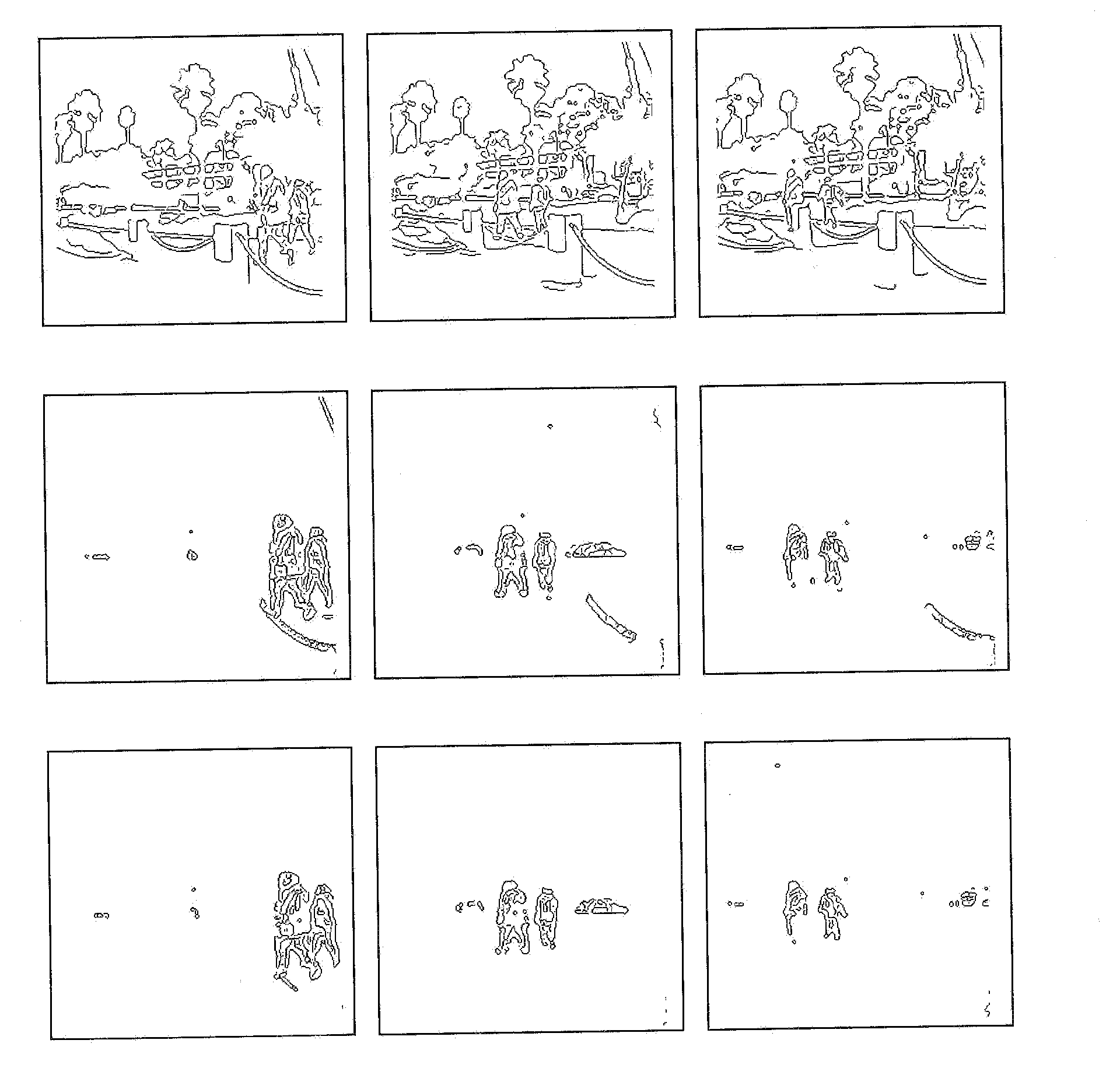
[0041]In this invention disclosure, using a spectral sensor for target detection and tracking based on the target spectral content change or variation is disclosed. The following general exemplary procedures are described for detecting and tracking a target via a spectral sensor 101.

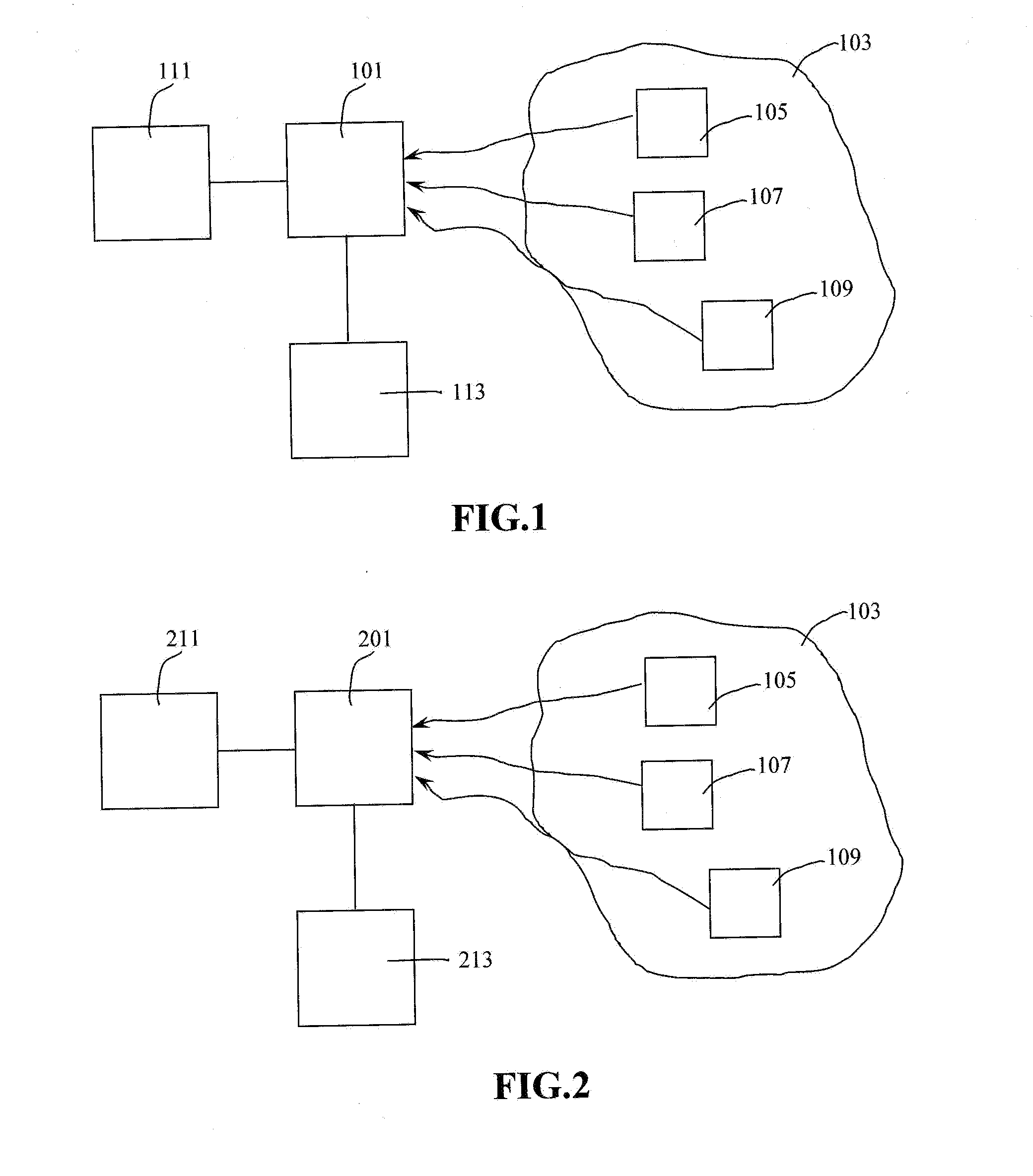
[0042]FIG. 1 illustrates a spectral sensor 101 which may be positioned to scan a first predetermined area 103 which may include a first object 105, a second object 107 and a third object 109 which may be referred to as targets. The first object 105, the second object 107 and the third object 109 may be a vehicle, an animal, a human, a building, trees and bushes or other types of objects.

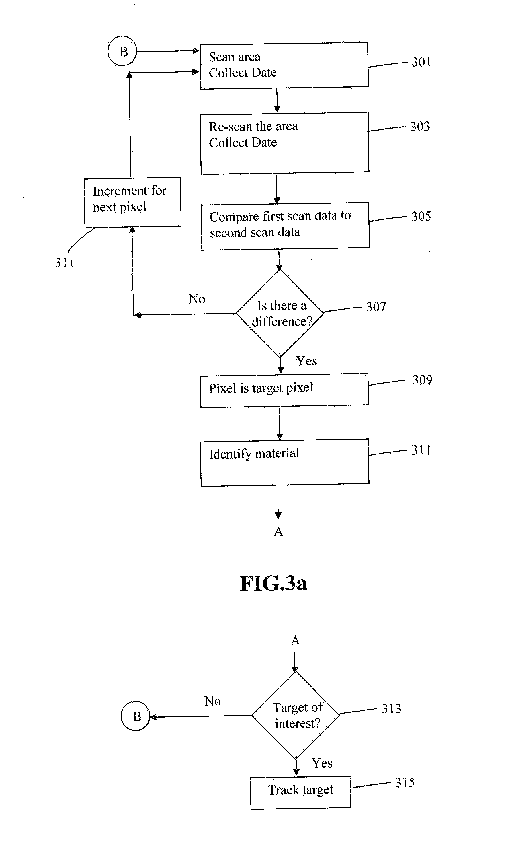
[0043]The sensor 101 performs a first scan at a first predetermined time over a wide predetermined area 103 to collect the first set of hyperspectral or multispectral data from at least the first object 105, the second object 107 and the third object 109 and which may be stored in a database 113.

[0044]The sensor 101 perfo...

second embodiment

[0052]In this invention disclosure as shown in FIG. 2, using for example a spectrally and spatially foveated multi / hyperspectral sensor 201 for target detection and tracking based on the spectral content change or variation of the target / object 105, 107, 109 is disclosed. The following procedures are for detecting and tracking a target / object 105, 107, 109 via such a spectrally and spatially foveated sensor 201. Exemplary approaches are suggested.

Detecting and Tracking a Moving Target by Using a Spectrally and Spatially Foveated Sensor

[0053]The sensor 201 monitors a wide area (wide FOV) in a first predetermined staring mode with programmable coarse and fine spatial resolution but without spectral scanning.[0054]The processor 111 which may be a sensor on-chip processor finds a moving target(s) 105, 107, 109 via the implemented algorithm, as described by J. T. Caulfield in Reference (2) which has been incorporated by reference in its entirety;

[0055]The sensor 201 by the processor 111 ...


PUM


Abstract

A method of operating a sensor system may include the steps of sensing a predetermined area including a first object to obtain first sensor data at a first predetermined time, sensing the substantially same predetermined area including the first object to obtain second sensor data at a second predetermined time, determining a difference between the first sensor data and the second sensor data, identifying a target based upon the difference between the first sensor data and the second sensor data, identifying a material of the target and determining a target of interest to track based upon the material of the target.

Description

PRIORITY[0001]The present invention claims priority under 35 USC section 119 and based upon a provisional application with a Ser. No. 61 / 281,097 which was filed on Nov. 12, 2009.FIELD OF THE INVENTION[0002]This invention relates to approaches for target tracking, classification and identification based on spectral, spatial and temporal content changes of an object by using spectrally and spatially foveated sensors.BACKGROUND INTRODUCTIONTarget Tracking, Classification and Identification Based on Spatial Content Changes[0003]In the conventional approach, a 2-D imaging sensor is employed to capture pictures of an object. The object is declared to be a target based on its spatial properties such as shape and spatial content. Detected changes relating to the object's position displacement, position displacement speed, position displacement direction and shape variation, etc. are all used for the purpose of target detection, tracking, classification and identification.[0004]For example, ...

Claims


Application Information

Patent Timeline
Patent Type & Authority Applications(United States)
IPC IPC(8): H04N5/225
CPCG01S3/786H04N5/23245H04N23/667
Inventor LI, LESWAMINATHAN, VENKATARAMANWILLSON, PAUL D.YU, HAIPINGWANG, SHENGGANGGUO, LEIDU, FANGLI, PENGMASSIE, MARK
Owner LI LE
Features
  • Generate Ideas
  • Intellectual Property
  • Life Sciences
  • Materials
  • Tech Scout
  • Unparalleled Data Quality
  • Higher Quality Content
  • 60% Fewer Hallucinations
Learn More