Heating apparatus and image forming apparatus

a technology of image forming apparatus and heating apparatus, which is applied in the direction of electrographic process apparatus, instruments, optics, etc., can solve the problems of overpowering the heating apparatus, the safety circuit using a temperature detection element such as a thermistor, and the insufficient response speed of the thermo switch, so as to increase the safety of the heating apparatus and simplify the configuration.

Inactive Publication Date: 2011-11-17
CANON KK
View PDF6 Cites 25 Cited by
  • Summary
  • Abstract
  • Description
  • Claims
  • Application Information

AI Technical Summary

Benefits of technology

[0007]In view of such circumstances, the present invention has been made, and an object of the present invention is to provide a heating apparatus capable of swit

Problems solved by technology

However, in the aforementioned method (configuration) of switching between the serial connection and the parallel connection, a failure in a supply voltage detection part or a resistance value switching relay may cause the heat

Method used


Image

  • Heating apparatus and image forming apparatus
  • Heating apparatus and image forming apparatus
  • Heating apparatus and image forming apparatus

Examples


first embodiment

[0030]Hereinafter, the configuration and the operation of the first embodiment will be described.

[0031]Heater Control Circuit

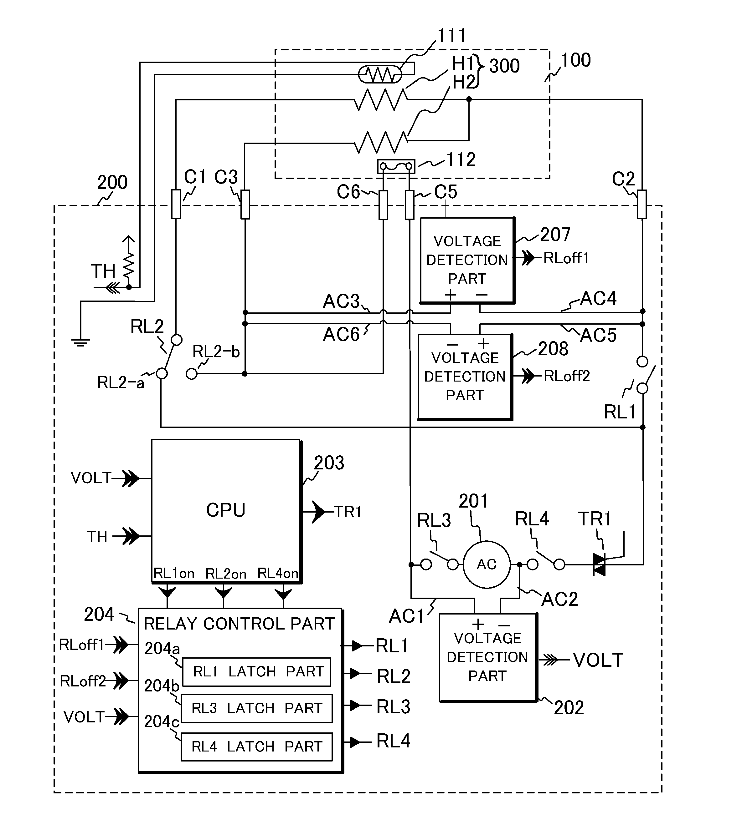
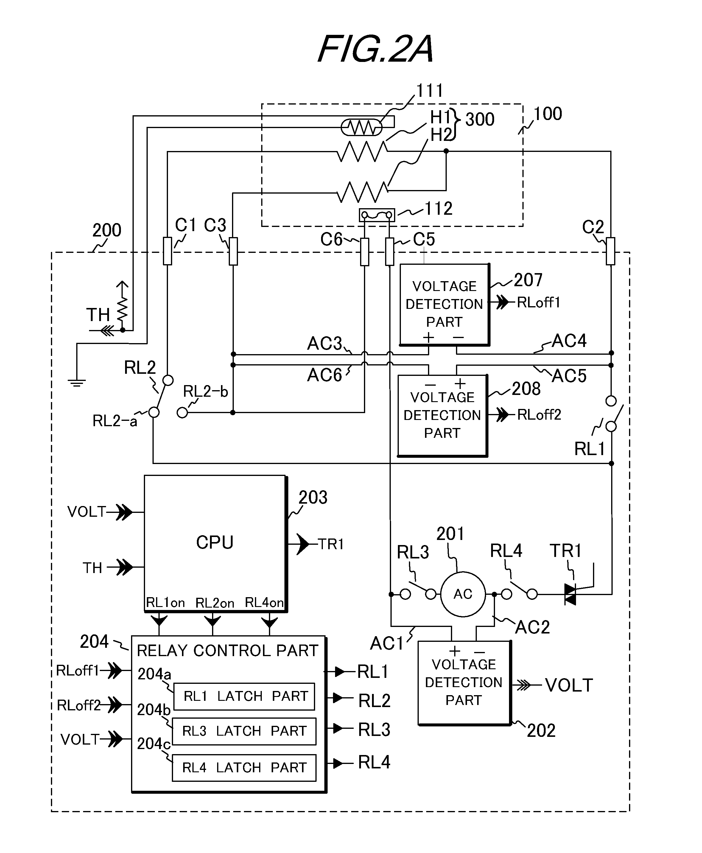
[0032]FIGS. 2A and 2B illustrate a control circuit 200 of the heater 300 according to the first embodiment. More specifically, FIG. 2A is a circuit block diagram for describing the control circuit 200; and FIG. 2B is a circuit diagram for describing a voltage detection part 202, a voltage detection part 207 and a voltage detection part 208. Connectors C1, C2, C3, C5 and C6 connect between the control circuit 200 and the fixing apparatus 100. Power control from a commercial AC power supply 201 to the heater 300 is performed by turning on and off a bidirectional thyristor (hereinafter referred to as a triac) TR1. The triac TR1 operates in response to a signal from the CPU 203 for driving the heater 300. The temperature detected by the temperature detection element 111 is detected as a voltage divided by a pull-up resistor and input to the CPU 203 as a TH signal....

second embodiment

[0056]Hereinafter, the configuration and the operation of a second embodiment will be described.

[0057]Heater Control Circuit

[0058]Note that the description of the configuration similar to that of the first embodiment is omitted, and the description will be given using the same reference numerals or characters. FIGS. 6A and 6B illustrate a heater 700 and a control circuit 600 respectively according to the second embodiment. FIG. 6A illustrates a heating pattern, a conductive pattern and an electrode formed on a substrate of the heater 700. The heater 700 includes current paths H1 and H2 each made of a resistance heating pattern. The heater 700 further includes a conductive pattern 703. Power is supplied to the current path H1 of the heater 700 through electrodes E1 and E2, and power is supplied to the current path H2 through electrodes E3 and E4. The electrode E1 is connected to the connector C1, the electrode E2 is connected to the connector C2, the electrode E3 is connected to the ...

third embodiment

[0065]Hereinafter, the configuration and the operation of the third embodiment will be described.

[0066]Current Detection Part 209

[0067]Note that the description of the configuration similar to that of the first embodiment is omitted, and the description will be given using the same reference numerals or characters. FIGS. 8A and 8B illustrate a control circuit 800 of the heater 300 according to the third embodiment. The current detection part 205 is the same as that of the second embodiment and thus the description thereof is omitted. The outputs Iin and Iref of the current transformer 206 are output to the current detection part 205 and the current detection part 209. FIG. 8B is a circuit diagram for describing the current detection part 209 detecting a negative half wave. FIG. 8B illustrates an example of the current detection part. When the value of a negative current flowing in the current path H2 becomes large, the value of a voltage (output voltage) of the output Iin of the cur...


PUM


Abstract

The heating apparatus includes a first detection part which detects whether or not the power supplied to the heat generation member is in an overpower state by detecting a positive phase of a half wave in an alternating voltage of a commercial power supply applied to the first or the second current path of the heat generation member, a second detection part which detects whether the power supplied to the heat generation member is in an overpower state or not by detecting a negative phase of a half wave in an alternating voltage the commercial power supply applied to the first current path or the second current path of the heat generation member, and a control part which controls itself to stop supplying power from the commercial power supply to the heat generation member in a case where an overpower state is detected by the first or second detection part.

Description

BACKGROUND OF THE INVENTION[0001]1. Field of the Invention[0002]The present invention relates to a heating apparatus for use in an image forming apparatus such as a facsimile machine and a laser beam printer.[0003]2. Description of the Related Art[0004]The image forming apparatus includes a heating apparatus used to heat and fix a toner image transferred to a recording material. The heating apparatus includes a nip portion made of a heating member maintained at a predetermined temperature and a pressure roller pressure-contacted with the heating member. The nip portion uses a process of heating a recording material while pinching and conveying the recording material as a heated material. Particularly, as the heating member of the heating apparatus using a film heating process, there is generally used a heater with a resistance heat generation member formed on a substrate such as a ceramic. When a heater with the same resistance value is used in the heating apparatus using a resistan...

Claims


Application Information

Patent Timeline
IPC IPC(8): G03G15/20
CPCG03G15/205G03G15/5004H05B1/0202G03G15/2039G03G15/5012G03G15/55G03G15/80G03G15/2053
Inventor SHIMURA, YASUHIRO
Owner CANON KK
Why Eureka
Try Eureka