Improved Rotor-Blade Control System and Method

a control system and rotor technology, applied in the direction of rotors, marine propulsion, vessel construction, etc., can solve the problems of rotors developing lift forces that vary across the plane of rotors

Active Publication Date: 2011-11-17
TEXTRON INNOVATIONS
View PDF1 Cites 18 Cited by
  • Summary
  • Abstract
  • Description
  • Claims
  • Application Information

AI Technical Summary

Problems solved by technology

On the other hand, tilting of the swashplate causes the pitch of each blade to change sinusoidally, or cyclically, as the rotor rotates, which causes the rotor to develop lift forces that vary across the plane of the rotor.

Method used


Image

  • Improved Rotor-Blade Control System and Method
  • Improved Rotor-Blade Control System and Method
  • Improved Rotor-Blade Control System and Method

Examples


Embodiment Construction

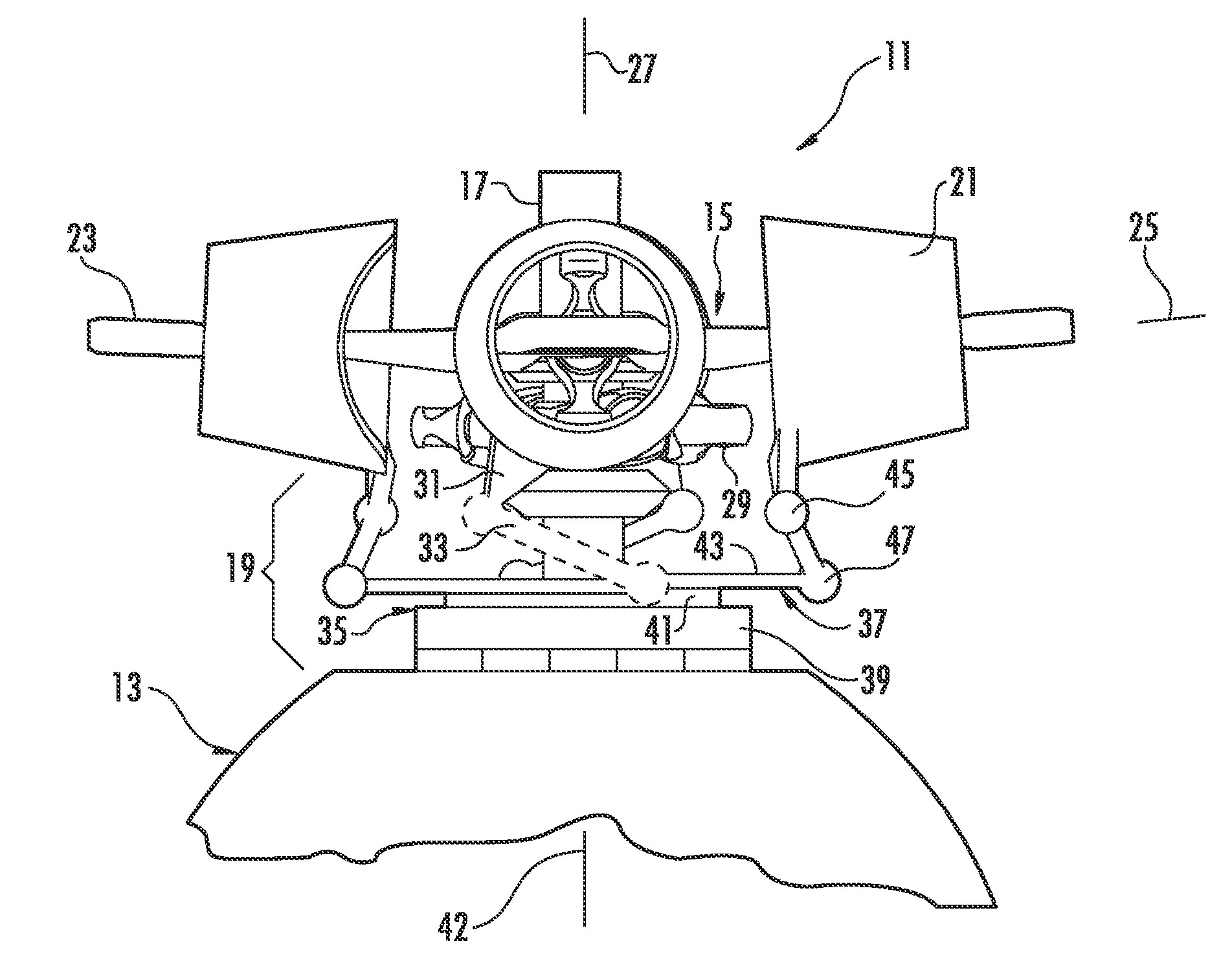
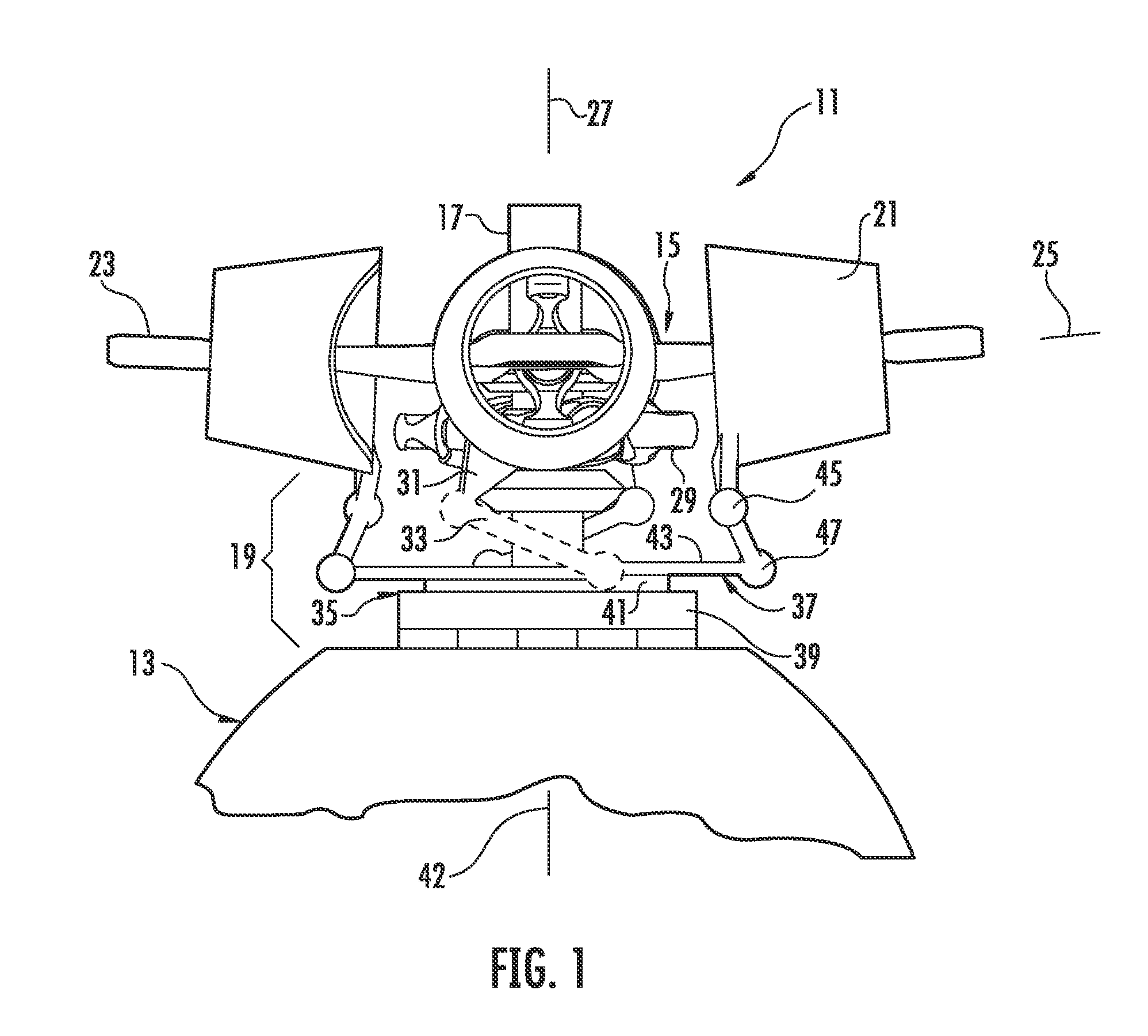
[0016]A blade-pitch control system is provided for a rotor having multiple blades that are each adjustable for pitch angle. Each blade is connected to a rotating swashplate of a swashplate assembly, and the rotating swashplate is configured for rotational indexing relative to the mast during rotation with the mast for collective pitch control of the blades.

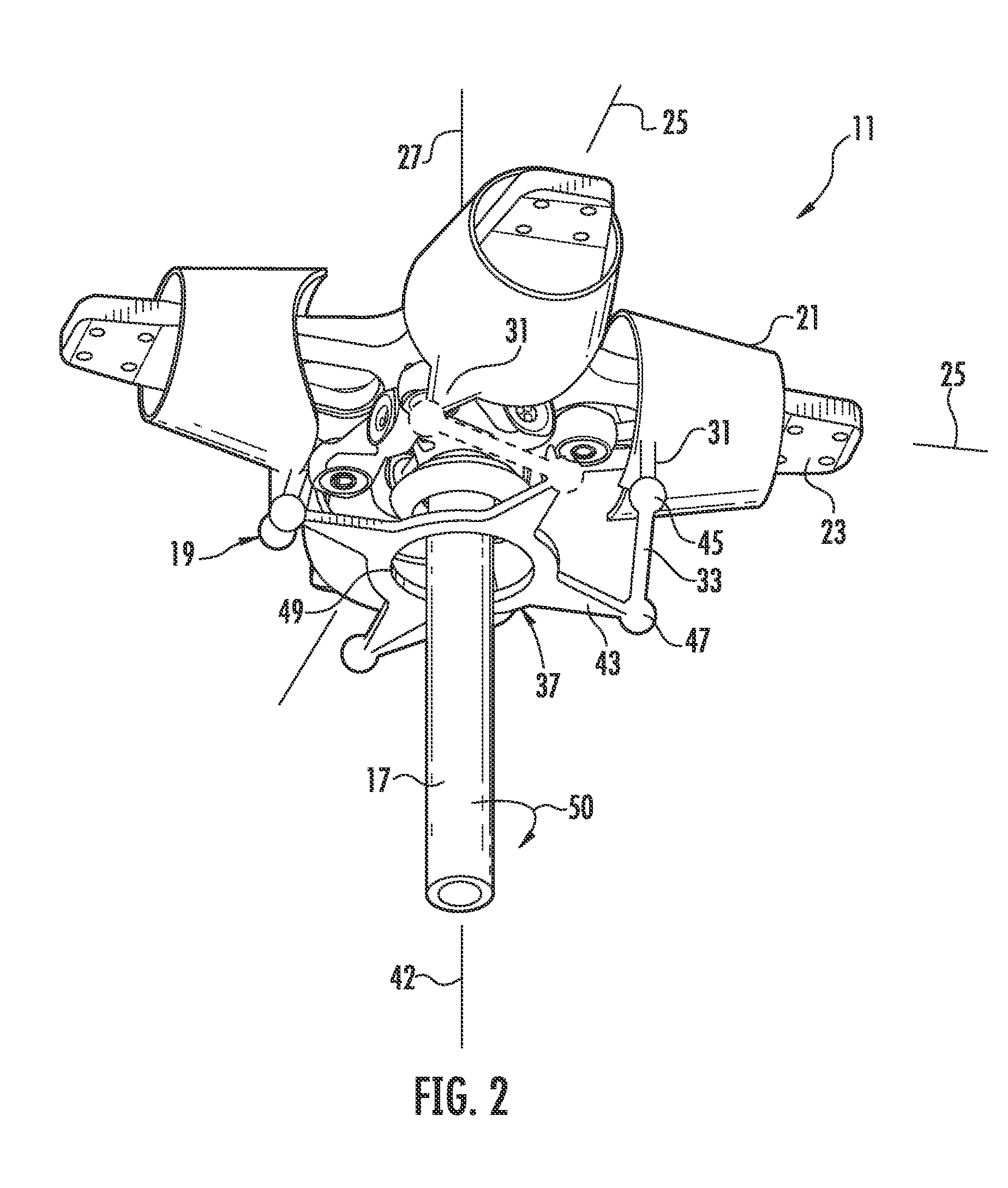
[0017]FIG. 1 is a side view of a rotor hub assembly 11 installed on a rotary-wing aircraft 13, such as a helicopter or tiltrotor, with hub assembly 11 comprising a rotor hub 15, mast 17, and an embodiment of a blade-pitch control system 19 for controlling the pitch of blade grips 21. Rotor blades (not shown) are attached to grips 21 (only inner portions are shown), and each blade and grip 21 are rotatably attached to a yoke 23 to allow for adjustability of pitch angle about a corresponding pitch axis 25. To allow for mast 17 to rotate yoke 23 about mast axis 27, yoke 23 is attached to mast 17 with a constant-velocity joint assembl...


PUM


Abstract

A blade-pitch control system has a swashplate configured for continuous rotation with an associated rotor and mast, and at least one link connects the swashplate to each blade of the rotor. The swashplate provides for collective control of the pitch angle of the blades through selective rotation of the swashplate about a swashplate axis while the swashplate is rotating with the rotor and mast. The system can be configured to provide for cyclic control of the pitch angle of the blades through planar translation of the swashplate or through tilting of the swashplate about axes generally perpendicular to the swashplate axis.

Description

TECHNICAL FIELD[0001]The technical field is control systems for rotors.DESCRIPTION OF THE PRIOR ART[0002]Rotary-wing aircraft, such as helicopters and tiltrotors, have at least one rotor for providing lift and propulsion forces. These rotors have at least two airfoil blades connected to a hub, and the hub is mounted on a rotatable mast driven in rotation by an engine. These blades may be adjustable for pitch angle, and the pitch angle is typically controlled by a swashplate assembly and linkage for connecting a rotating portion of the swashplate assembly to each blade.[0003]One example of a prior-art system includes a swashplate movable in directions parallel to the mast axis toward and away from the rotor for collective control and tilts about axes perpendicular to the mast axis for cyclic control. When the swashplate moves toward or away from the rotor, the pitch angle of each blade changes by the same amount, and in the same direction, as each other blade. This collective control...

Claims


Application Information

Patent Timeline
Patent Type & Authority Applications(United States)
IPC IPC(8): F04D29/36
CPCB64C27/605B64C27/32
Inventor STAMPS, FRANK B.RAUBER, RICHARD E.
Owner TEXTRON INNOVATIONS
Why Eureka
Try Eureka