Supercharge Your Innovation With Domain-Expert AI Agents!

High speed electrical contact assembly

a high-speed, electrical contact technology, applied in the direction of coupling device connection, coupling parts engagement/disengagement, connection formation by deformation, etc., can solve problems such as signal deformation

Active Publication Date: 2011-11-17
AMPHENOL CORP
View PDF6 Cites 5 Cited by
  • Summary
  • Abstract
  • Description
  • Claims
  • Application Information

AI Technical Summary

Benefits of technology

The present invention provides a contact assembly that includes an outer body and an insert assembly that is receivable in the outer body. The insert assembly has a housing and a conductive barrier that defines first and second receiving areas in the housing. Each of the first and second contact members is adapted to accept a conductor. The contact assembly may be a plug assembly or a socket assembly. The invention also provides a method for assembling a contact assembly that includes an outer body, first and second insulator halves, a conductive barrier, and first and second contacts. The technical effects of the invention include improved electrical connection and reliable grounding, as well as simplified assembly and disassembly processes.

Problems solved by technology

At higher speeds, however, the signal degrades due to crosstalk interference between conductors.

Method used


Image

  • High speed electrical contact assembly
  • High speed electrical contact assembly
  • High speed electrical contact assembly

Examples


Embodiment Construction

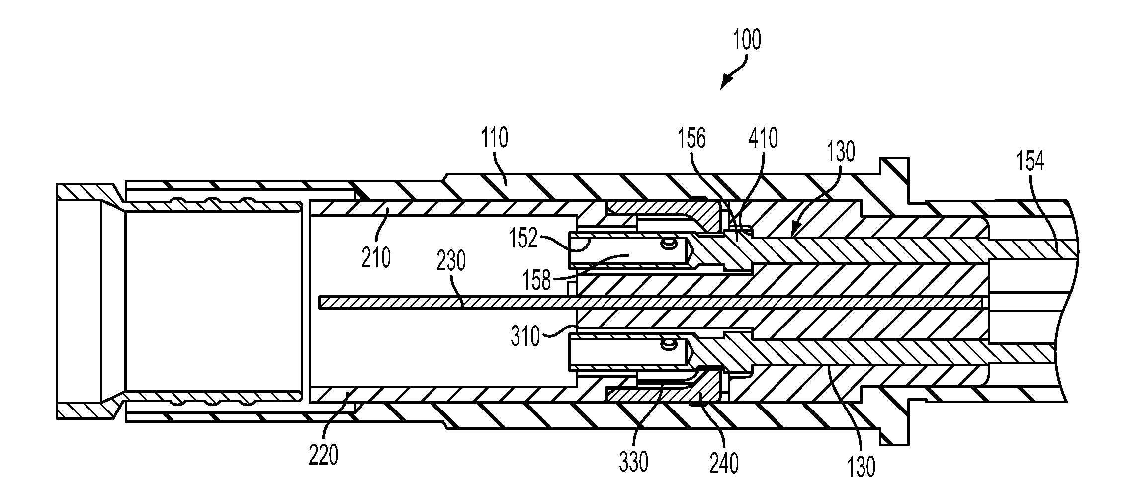
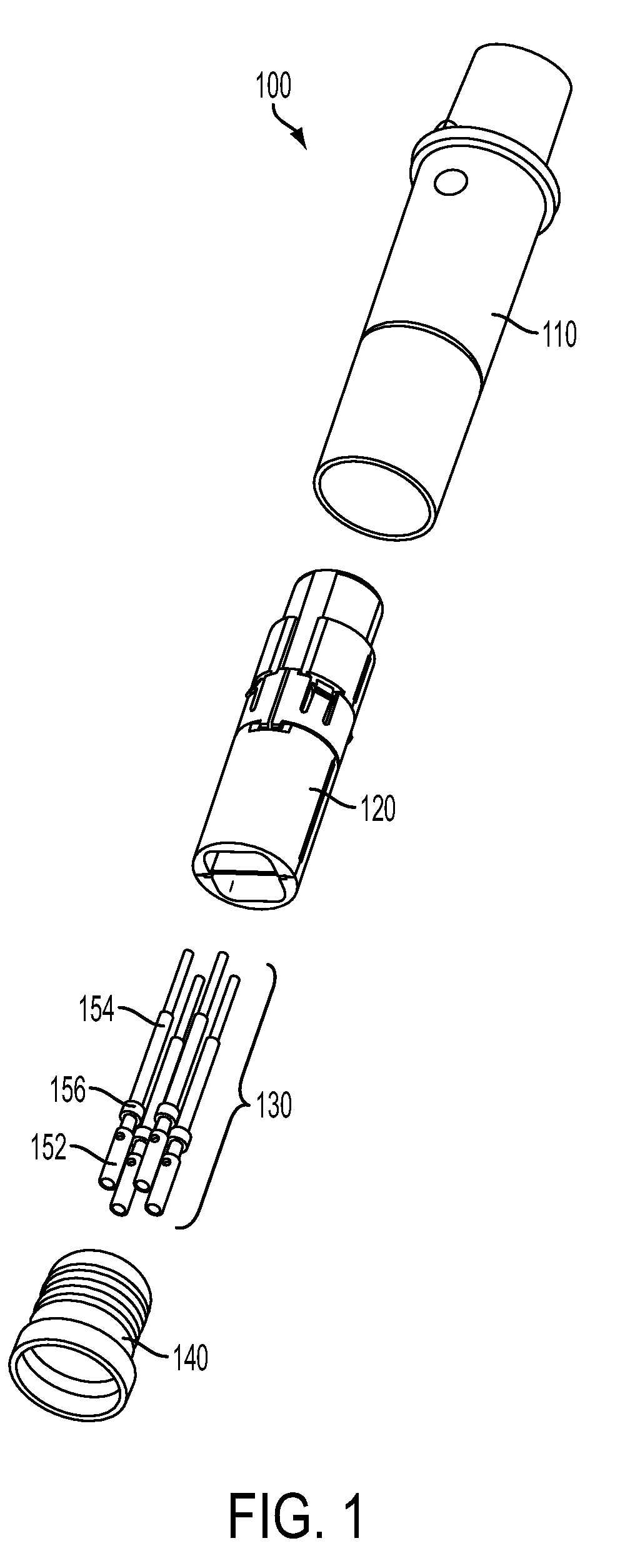
[0021]Referring to FIGS. 1-4, a contact assembly 100 according to an exemplary embodiment of the present invention is designed to reduce crosstalk between conductors, thereby allowing for much higher data transfer speeds than conventional contacts and connectors. The contact assembly 100 may generally include an outer body 110, an insert assembly 120, a plurality of contact members 130, and a crimp ferrule 140, as best seen in FIG. 1.

[0022]The outer body 110 may be a connector shell, such as the plug shell illustrated in FIG. 1. The outer body 110 is adapted to receive the insert assembly 120 and the contact members 130. The outer body 110 is preferably made of a metal, such as s copper allow like beryllium copper, leaded-nickel copper, phosphor bronze, or tellurium copper. The outer body 110 is sized such that it may be retrofit into existing connector contact cavities.

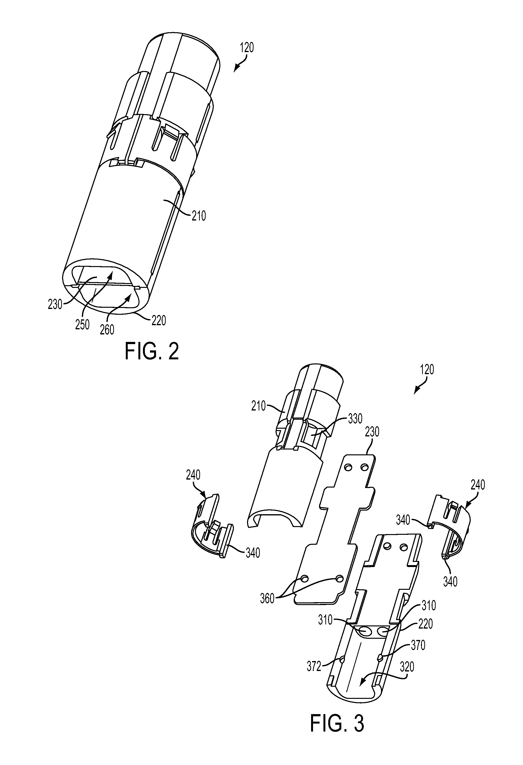
[0023]As seen in FIGS. 2 and 3, the insert assembly 120 generally includes a housing defined by first and second i...


PUM

PropertyMeasurementUnit
areaaaaaaaaaaa
conductiveaaaaaaaaaa
speedaaaaaaaaaa

Abstract

A contact assembly that comprises an outer body and an insert assembly receivable in the outer body. The insert assembly includes a housing and a conductive bather received in the housing. The conductive barrier defines first and second receiving areas in the housing. At least a first contact member is receivable in the first receiving area and at least a second contact member is receivable in the second receiving area. Each of the first and second contact members is adapted to accept a conductor.

Description

RELATED APPLICATION[0001]This application claims priority under 35 U.S.C. §119 to U.S. Provisional Application Ser. No. 61 / 333,961, filed on May 12, 2010, entitled High Speed Electrical Contact Assembly.FIELD OF THE INVENTION[0002]The invention relates to an electrical contact assembly that accommodates high speed data transfer.BACKGROUND OF THE INVENTION[0003]Current connection systems require increasingly higher reliability and data speed transmission. For example, current connection systems are required to meet standards, such as IEEE 802.3. IEEE 802.3 is a collection of standards relating Ethernet, which is one of the most common computer-to-computer data communication methods. At higher speeds, however, the signal degrades due to crosstalk interference between conductors. That is particularly the case where the conductors are untwisted and terminated to a connector, such as a plug or socket.[0004]Therefore, a need exists for a contact assembly that can accommodate high data spe...

Claims


Application Information

Patent Timeline
Patent Type & Authority Applications(United States)
IPC IPC(8): H01R24/00H01R43/04H01R13/62
CPCH01R13/65807H01R43/20H01R13/6585H01R13/6461Y10T29/49218
Inventor PHILLIPS, DAVID A.JOHNSON, HEATH A.
Owner AMPHENOL CORP
Features
  • R&D
  • Intellectual Property
  • Life Sciences
  • Materials
  • Tech Scout
  • Unparalleled Data Quality
  • Higher Quality Content
  • 60% Fewer Hallucinations
Learn More