Coaxial connector

a technology of coaxial connectors and connectors, applied in the direction of coupling devices, two-part coupling devices, electrical apparatus, etc., can solve the problems of high production cost, inability to guarantee grounding, and difficult assembly of conventional coaxial connectors, so as to reduce the stock of components, ensure grounding, and facilitate the effect of assembling and disassembling the devi

Inactive Publication Date: 2011-11-17
YANTEL CORP
View PDF0 Cites 12 Cited by
  • Summary
  • Abstract
  • Description
  • Claims
  • Application Information

AI Technical Summary

Benefits of technology

Advantages of the invention are summarized below. The pair of metal fixings of the coaxial connector is suitable for different thickness of substrates, thereby reducing the stocks of elements. The assembling and disassembling of the device is easy, the grounding is secure, and thus high accuracy and high electrical performance of coaxial connectors are achieved. The device is particularly suitable for the preparation of fixed attenuator with different frequency range.

Problems solved by technology

The higher the frequency range, the thinner the ceramic substrates should be, and thus the higher the production cost is.
Conventional coaxial connectors are very difficult for assembling, and if the two slots in the hollow copper column are processed with errors, the grounding cannot be guaranteed.
If assembled coaxial fixed attenuators are tested to have poor performance, the disassembling is unavoidable, which takes time and may destroy the attenuators.

Method used


Image

  • Coaxial connector
  • Coaxial connector
  • Coaxial connector

Examples


Embodiment Construction

For further illustrating the invention, experiments detailing a coaxial connector are described below. It should be noted that the following examples are intended to describe and not to limit the invention.

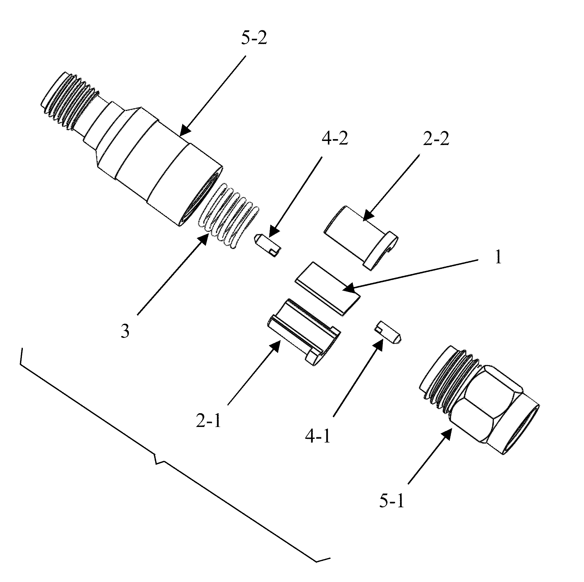
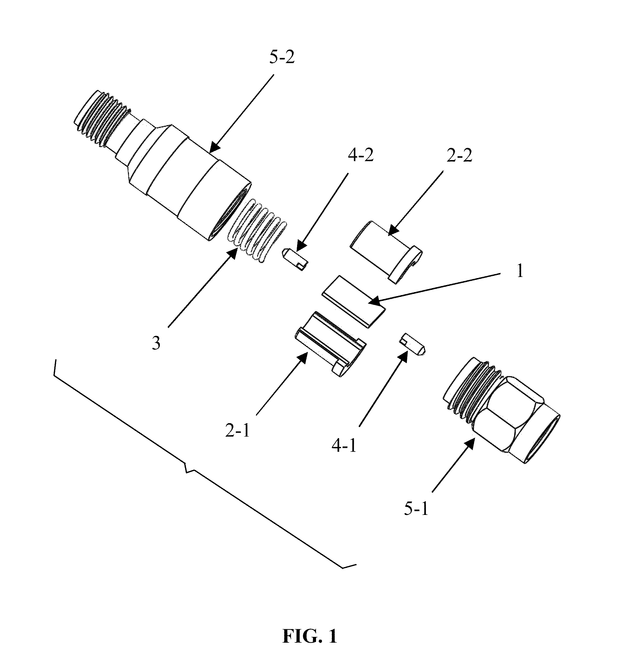
As shown in FIG. 1, an exploded view of a coaxial connector according to one embodiment of the invention. The coaxial connector comprises a first element 1, a pair of metal fixings 2-1, 2-2, an elastic fixing member 3, two metal joints 4-1, 4-2, a first metal shell 5-1, and a second metal shell 5-2.

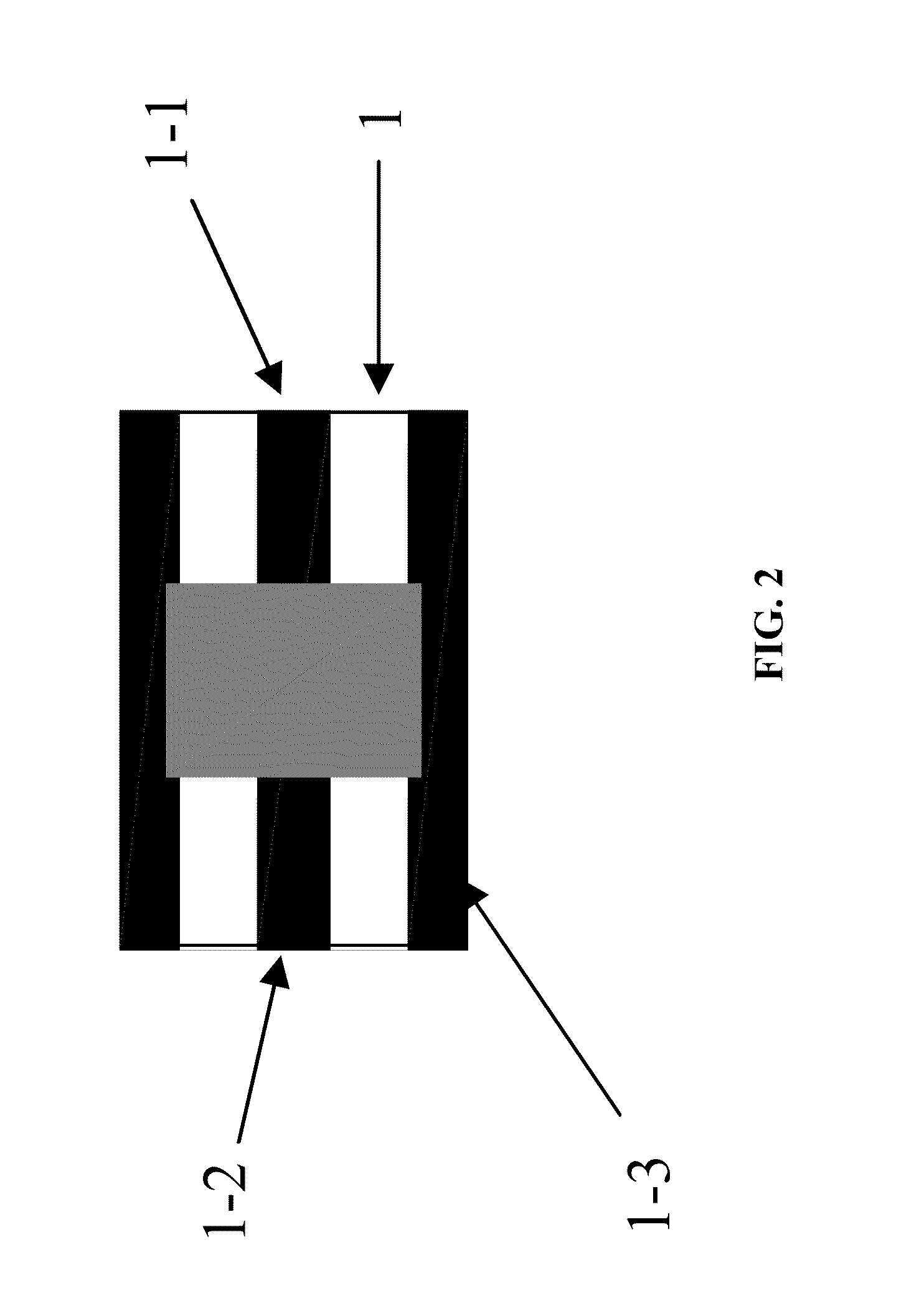
The first element 1 may be an attenuator, a wave filter, an impedance converter, or something like that. The first element 1 comprises a circuit substrate, a signal input terminal, a signal output terminal, and a grounding terminal. One end of each of the two metal joints 4-1, 4-2 contacts with the signal input terminal and the signal output terminal of the first element 1, respectively. The first element 1 is sandwiched between the pair of metal fixings 2-1, 2-2. The grounding terminal...


PUM


Abstract

A coaxial connector including a first element, two metal joints, a first metal shell, a second metal shell, an elastic fixing member, and a pair of metal fixings. The first element includes a circuit substrate, a signal input terminal, a signal output terminal, and a grounding terminal and is sandwiched between the pair of the metal fixings. The elastic fixing member embraces the pair of the metal fixings. One end of each of the two metal joints contacts with the signal input terminal and the signal output terminal of the first element, respectively, and the other end thereof contacts with a signal terminal of the first metal shell and the second metal shell, respectively. The pair of the metal fixings each contacts with the inner conductor of the first metal shell and the second metal shell. The coaxial connector is applicable to different thicknesses of substrates, and is easy to assemble and disassemble.

Description

BACKGROUND OF THE INVENTION1. Field of the InventionThe invention relates to a coaxial connector for electronic and communications devices, and more particularly to a coaxial connector for high frequency and microwave circuits and systems.2. Description of the Related ArtCoaxial connectors have been widely used in RF devices and systems. In order to produce high accuracy attenuation and low reflection coefficient of coaxial attenuators, it is urgent to improve the internal structure of coaxial connectors.Conventional coaxial fixed attenuator includes a hollow copper column in which an attenuator is disposed. The hollow copper column has two slots, and the attenuator is firmly fixed in the hollow copper column using two flexible beryllium copper gaskets.To make high frequency range of attenuators, thin ceramic substrates are often employed. The higher the frequency range, the thinner the ceramic substrates should be, and thus the higher the production cost is. To meet different requi...

Claims


Application Information

Patent Timeline
Patent Type & Authority Applications(United States)
IPC IPC(8): H01R9/05
CPCH01R24/42H01R2103/00H01R24/542
Inventor YAN, YUEJUN
Owner YANTEL CORP
Why Eureka
Try Eureka