
Outboard motor and marine vessel including the same

a technology for outboard motors and marine vessels, applied in the direction of marine propulsion, vessel construction, electric control, etc., can solve the problems of large insufficient reduction of the load applied to the tilt rod, so as to achieve the effect of not reducing the engine speed

Active Publication Date: 2011-11-17
YAMAHA MOTOR CO LTD
View PDF12 Cites 9 Cited by
  • Summary
  • Abstract
  • Description
  • Claims
  • Application Information

AI Technical Summary

Benefits of technology

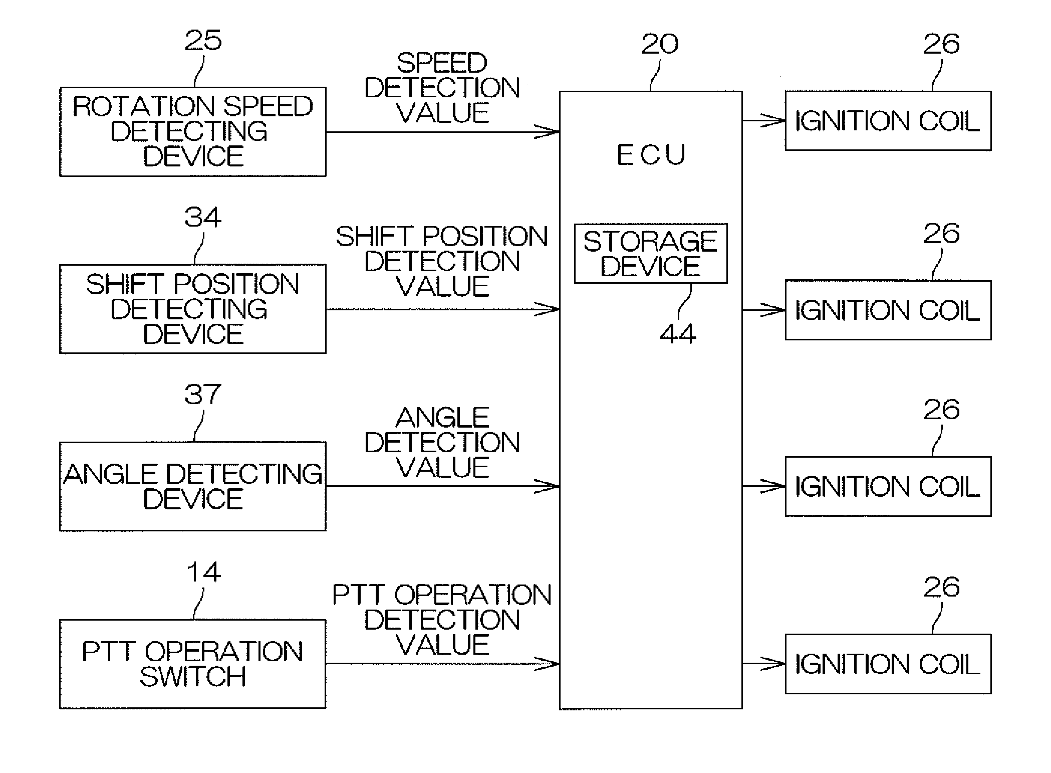
[0013]When an abnormality occurs in the angle detecting device, the angle detecting device outputs the angle detection value corresponding to the inclination angle less than the first angle or the angle detection value corresponding to the inclination angle greater than the second angle. The controller executes, in accordance with the angle detection value input from the angle detecting device and the speed detection value input from the speed detecting device, the speed reduction control to control the engine so as to reduce the engine speed. Specifically, the controller does not execute the speed reduction control when the angle detection value is the value corresponding to the inclination angle less than the first angle or the value corresponding to the inclination angle greater than the second angle. That is, the speed reduction control is not executed when an abnormality occurs in the angle detecting device. Thus, forcible reduction in the propulsive force is prevented when, for example, the outboard motor is driven forward at an ordinary speed. An adequate propulsive force can thus be obtained when necessary.
[0017]When the outboard motor main body generates a propulsive force, the propulsive force is transmitted from the outboard motor main body to the pivoting mechanism. Also, the propulsive force transmitted to the pivoting mechanism is transmitted to the attachment mechanism and the hull. Thus, when the outboard motor main body generates the propulsive force, a load is transmitted to the pivoting mechanism, the attachment mechanism, and the hull. With the arrangement of the present preferred embodiment, the engine speed is controlled so that the load applied to the pivoting mechanism, the attachment mechanism, and the hull is less than the load at which at least one component among the pivoting mechanism, the attachment mechanism, and the hull breaks. Breakage of the pivoting mechanism, the attachment mechanism, and the hull is thereby prevented. Specifically, for example, deformation of a rod of the first cylinder of the pivoting mechanism or damaging of the first cylinder is prevented. Also, for example, deformation of the fixed member or the horizontal shaft of the attachment mechanism is prevented. Also, for example, deformation or breakage of a rear portion (transom) of the hull is prevented.
[0021]In a case in which the controller judges that the angle detecting device is not operating normally, the controller does not execute the speed reduction control. That is, in the case in which the controller judges that the angle detecting device is not operating normally, the controller does not forcibly reduce the engine speed. Thus, for example, forcible reduction in the propulsive force due to an abnormality (for example, seizing) of the angle detecting device can be prevented when the outboard motor is driving the hull forward at an ordinary speed. An adequate propulsive force can thereby be obtained when necessary.
[0023]With the arrangement of the present preferred embodiment, the outboard motor main body includes the forward-reverse switching mechanism. The forward-reverse switching mechanism switches among the plurality of states that include the forward drive state, in which the outboard motor main body generates a forward driving force that propels the hull forward, and the reverse drive state, in which the outboard motor main body generates a reverse driving force that propels the hull in reverse. When the forward-reverse switching mechanism is not in the forward drive state, the controller does not execute the speed reduction control. Thus, the engine speed is not reduced forcibly when the forward-reverse switching mechanism is in the reverse drive state and the outboard motor main body generates the reverse driving force that propels the hull in reverse. Forcible reduction in the propulsive force (reverse driving force) can thus be prevented when the outboard motor is driving the hull in reverse.
[0024]Another preferred embodiment of the present invention provides a marine vessel including the outboard motor and a hull to which the outboard motor is attached. With this arrangement, the same effects as the above-mentioned effects can be achieved.

Problems solved by technology

Thus, in the state in which the outboard motor main body and the swivel bracket are tilted up, a large load is applied to the tilt rod.
However, when a sudden load is applied to the tilt rod, pressure release by the relief valve lags behind and a large load is applied to the tilt rod because the load applied to the tilt rod is not adequately reduced.
Thus, when, for example, a fault occurs in the trim sensor, a value differing from the angle detection value corresponding to the actual inclination angle of the outboard motor main body and the swivel bracket may be input into the controller and the outboard motor main body and the swivel bracket may thereby be erroneously judged as being tilted up even when these components are not tilted up.
Thus, for example, the engine speed may forcibly be reduced so that an adequate propulsive force cannot be obtained even when the outboard motor main body and the swivel bracket are not tilted up during ordinary marine vessel running, etc.

Method used


Image

  • Outboard motor and marine vessel including the same
  • Outboard motor and marine vessel including the same
  • Outboard motor and marine vessel including the same

Examples


Embodiment Construction

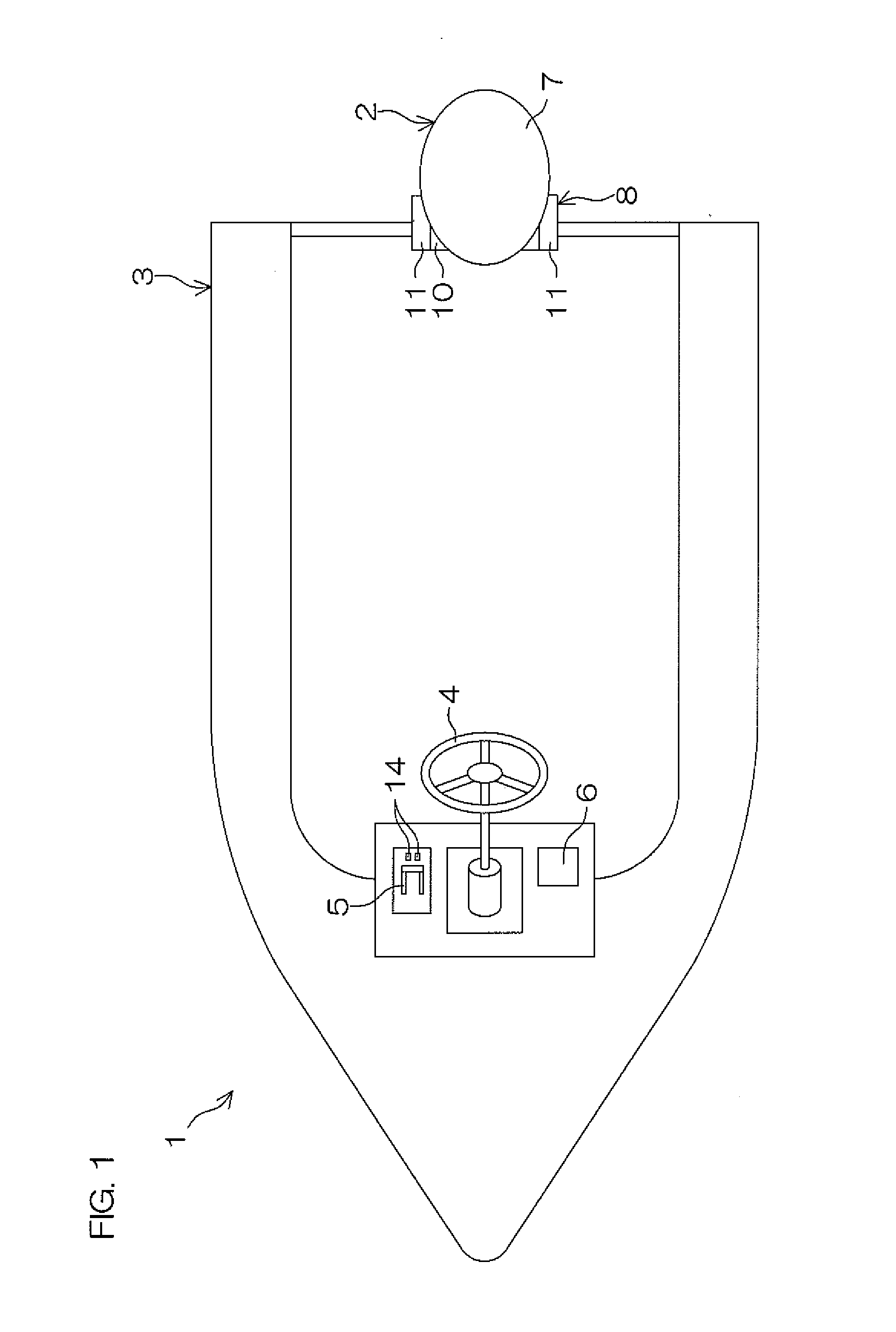
[0036]FIG. 1 is a conceptual diagram for explaining an arrangement of a marine vessel 1 according to a preferred embodiment of the present invention.

[0037]The marine vessel 1 includes the outboard motor 2 and the hull 3. The outboard motor 2 is attached to a rear portion of the hull 3. The hull 3 is propelled by the outboard motor 2. The hull 3 includes a steering member 4, a control lever 5, and a display portion 6. The marine vessel 1 is steered by the steering member 4 being operated. A speed of the marine vessel 1 is adjusted by the control lever 5 being operated. Switching between forward drive and reverse drive of the marine vessel 1 is performed by the control lever 5 being operated. The speed and other conditions of the marine vessel 1 are displayed on the display portion 6.

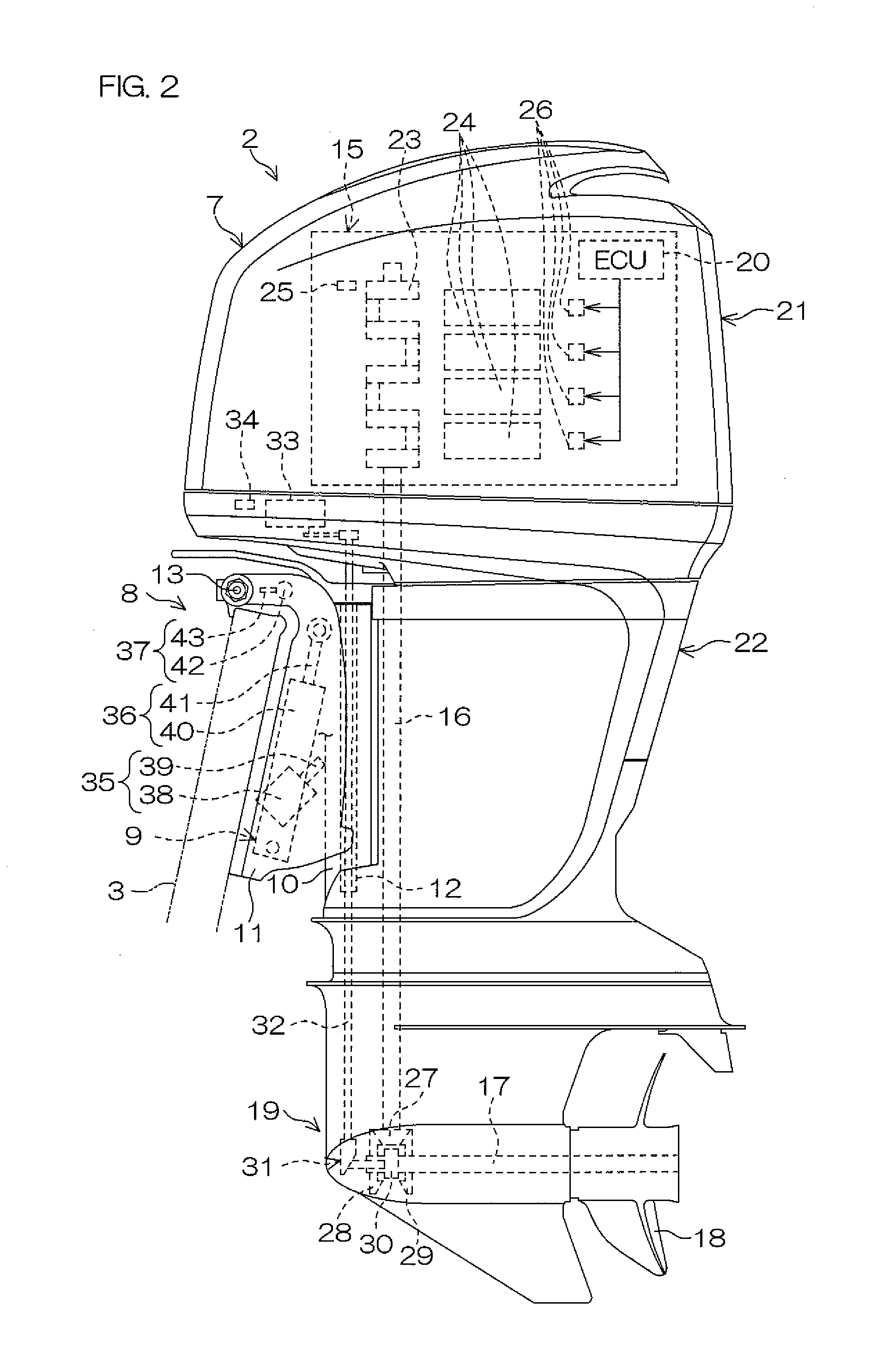
[0038]FIG. 2 is a side view of the outboard motor 2 according to a preferred embodiment of the present invention.

[0039]The outboard motor 2 includes an outboard motor main body 7, an attachment mechanism ...


PUM


Abstract

An outboard motor includes an outboard motor main body, an attachment mechanism, a pivoting mechanism, an angle detecting device, a rotation speed detecting device, and a controller. The pivoting mechanism includes a first cylinder arranged to support and pivot the outboard motor main body about a horizontal shaft from a first angle to a second angle greater than the first angle. An angle detection value and a speed detection value are input into the controller. The controller is arranged to execute a speed reduction control to control the engine so as to reduce the engine speed. The controller is arranged not to execute the speed reduction control when the angle detection value is a value corresponding to the inclination angle less than the first angle or a value corresponding to the inclination angle greater than the second angle.

Description

BACKGROUND OF THE INVENTION[0001]1. Field of the Invention[0002]The present invention relates to an outboard motor and a marine vessel including the same.[0003]2. Description of the Related Art[0004]An outboard motor is an example of a propulsion machine included in amarine vessel. A conventional outboard motor is described in U.S. Pat. No. 4,861,291. The outboard motor includes an outboard motor main body that generates a propulsive force by rotating a propeller by means of an engine. The outboard motor main body is supported by a swivel bracket via a steering shift. The swivel bracket is supported by a support bracket via a horizontal shaft. The support bracket is fixed to a hull. The outboard motor main body and the swivel bracket are pivotable up and down about the horizontal shaft with respect to the support bracket.[0005]The outboard motor main body and the swivel bracket are pivoted up and down about the horizontal shaft within a trim range by a trim cylinder. The outboard mo...

Claims


Application Information

Patent Timeline
Patent Type & Authority Applications(United States)
IPC IPC(8): B63H21/21
CPCF02D29/02F02D31/002F02D41/021F02D2041/227F02B61/045F02N2200/124B63H20/10B63H21/21F02D2200/101
Inventor INOUE, HIROSHIWATANABE, YOSHIKAZU
Owner YAMAHA MOTOR CO LTD
Learn More