
System and method for prevention and control of the effects of spatial disorientation

a technology of spatial disorientation and control method, applied in the field of system and method for preventing and controlling the effects of spatial disorientation, can solve the problems of more susceptible, poor ventilation, and more severe motion sickness

Active Publication Date: 2011-11-17
IARMORHLDG INC +2
View PDF12 Cites 63 Cited by
  • Summary
  • Abstract
  • Description
  • Claims
  • Application Information

AI Technical Summary

Problems solved by technology

Some are more susceptible due to physical reasons such as age.
It has been well observed that poor ventilation, bad odors, smoking, eating large fatty meals and alcohol can make motion sickness more pronounced.
However, many adults remain highly sensitive caused by any motion, particularly when combined with either an absence of a visual reference or to significant levels of visual stimuli.
Some people can get sick just thinking about an upcoming trip or flight.
For those who experience the symptoms, the result is often disabling, with nausea, vomiting, sweating, and unsteadiness, while feeling cold, clammy and disorientated.
This becomes a major problem in modern seamanship in which small crews are responsible for the operation of sensitive and sophisticated equipment.
The soldiers were lying and sitting in flat bottomed crafts and were using huge buckets for vomiting and urinating, which soon overflowed after boarding.
Spatial disorientation along with motion sickness are significant problems in aviation.
In motion provocative environments, spatial disorientation and motion sickness cause not only a loss in human performance (affecting cognitive and motor skills), but a loss of expensive aircraft and human life.
More significantly, Nine (9) out of ten (10) SD mishaps result in a fatality.
Airsickness has also been identified as a flight training issue.
This lack of congruence between sensory exposure to provocative real or apparent motion leads to the progressive cardinal symptoms of terrestrial motion sickness.
More recently, simulator sickness in virtual environments (VE) has become an important issue.
However, some users of VE experience discomfort during, and sometimes after, a session in a simulated environment, in equivalent fashion to simulator sickness already noted for flight and driving simulators.
One such theory suggested that vascular deficiency was due to the irritation of the eyes by perceived motion, which, by reflex action, produced spasm in the cerebral capillaries causing giddiness and vomiting.
Investigators now also agree that it is primarily an incongruence of visual and vestibular sensory information regarding movement and orientation that results in motion sickness.
However some patients, particularly non-Meniere's disease patients, have a prolonged period of unsteadiness without compensation for a long period of time.
The resulting disability can be devastating.
It has also been shown that postural instability precedes motion sickness with provocative visual stimuli.
All these vestibular impairments cause disequilibrium, blurred vision, disorientation, and vertigo, which in turn cause dysfunction in many activities of daily living and in social interactions that traditional medical treatments may not address.
Mismatches can occur where there is motion, or where there is no motion.
These mismatches may be caused by delays in the delivery or processing of the stimuli or mismatch of stimuli even without delay.
However Butnaru system of cues have been determined to have some limitations and the Butnaru system is lacking in its integration with user environments, which may cause sensory mismatches.

Method used


Image

  • System and method for prevention and control of the effects of spatial disorientation
  • System and method for prevention and control of the effects of spatial disorientation
  • System and method for prevention and control of the effects of spatial disorientation

Examples


embodiment 390

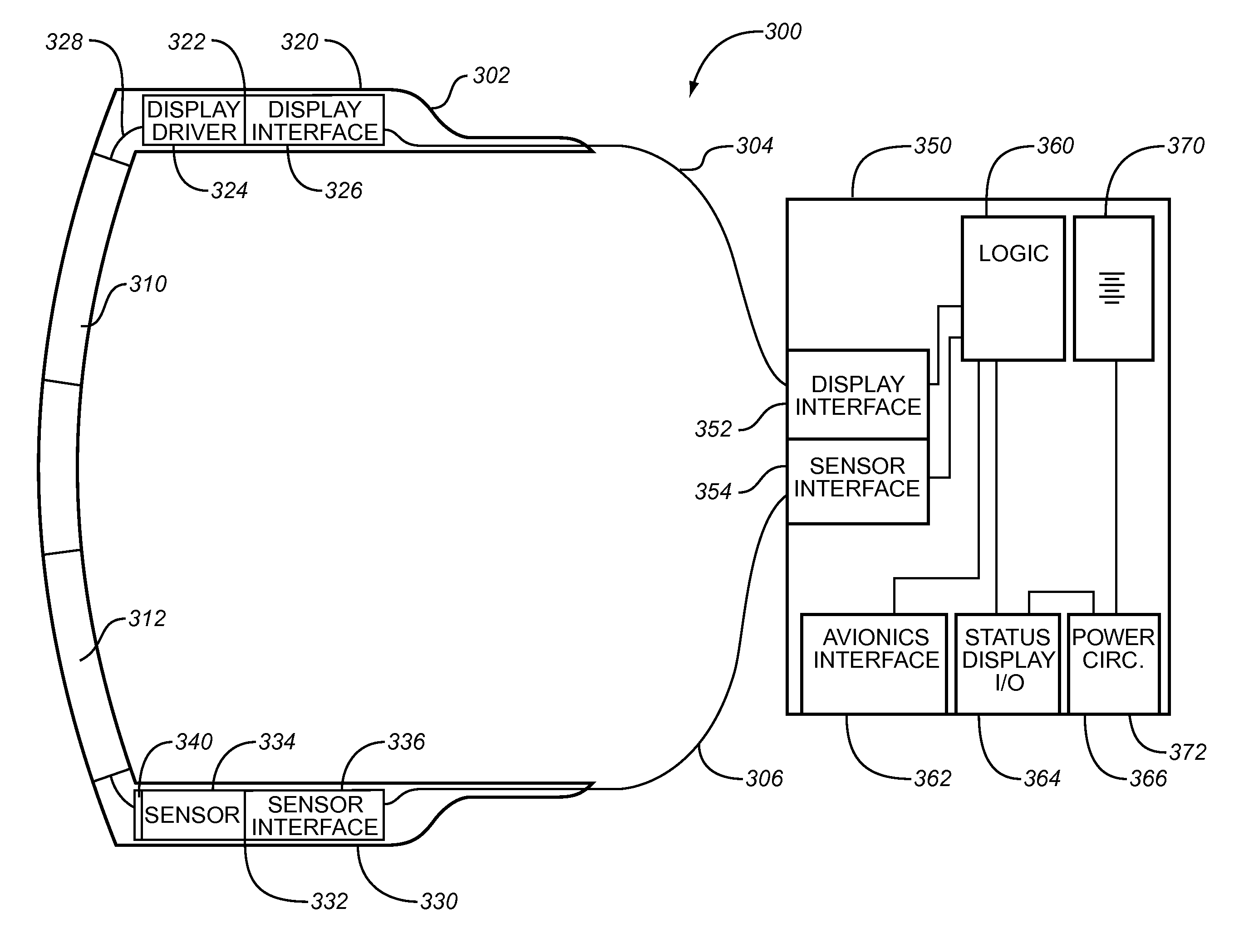
[0059]FIG. 5 illustrates yet a further embodiment 390 of an eyeglass headwear 391 implementation of the avionics subsystem. This embodiment further employs the use of eye sensors 392, 393. In one embodiment these sensor 392, 393 take the form of video cameras, which records images of the user's eyes as they move during use of the system. The video cameras are controlled by camera driver circuitry 394 and video interface circuitry 395 which interfaces with video interface circuitry 398 in the logic / power dongle 399 via umbilical electrical connection 396. The logic circuitry in the dongle 399 monitors ocular parameters like eye vertical (up and down) and horizontal (left and right), combined vertical and horizontal, and rotational eye movement and pupil dilation. This embodiment also includes inertial sensors 340 in the bridge of the headwear 391 and associated sensor circuitry 386 and interface circuitry 384 for interfacing with the logic and power dongle 399 via electrical connecti...

embodiment 400

[0060]FIG. 6 illustrates a HMD (helmet mounted display) embodiment 400 of the headwear portion of an avionics subsystem. This embodiment includes a helmet 402 with a visor 404 onto which data can be displayed in display regions 406 and 408. The helmet 402 is also configured with eye sensors 410 and 411 which track ocular parameters such as pupil size and eye movement. The inertial sensors 340 are also helmet mounted. The element connected to the other avionics systems and subsystems via an umbilical 412 that contains electrical and optical conduits (not shown) for communication. For avionics applications of the user stabilization system taught herein, the HMD embodiment of the headwear portion of the subsystem is preferable for fighter applications such as for the 5th Generation Fighters where helmets are traditionally used. The eyeglass embodiments illustrated in FIG. 3, FIG. 4 and FIG. 5 may be better suited for what is sometimes called shirt-sleeve environment applications: both ...


PUM


Abstract

An improved System and Method to provide a human user with symbology to ameliorate, prevent or shorten the duration of disorientation or motion sickness effects caused by spatial disorientation.

Description

RELATED APPLICATION(S)[0001]This application claims priority of Provisional Application Ser. No. 61 / 345,040 filed on 14 May 2010.TECHNICAL FIELD OF THE INVENTION[0002]The present invention generally relates to systems and methods for avoiding problems associated with compromise or human performance or loss of control due to vertigo, motion sickness and spatial disorientation.BACKGROUND OF THE INVENTION[0003]Motion sickness, spatial disorientation and vertigo have been acknowledged as a wide-spread problem, affecting a significant portion of world population to varying degrees. Researchers report that up to 60% of the population have some motion intolerance. It has been reported that motion sickness affects nearly one third of all people who travel by land, sea, or air. Individuals are affected daily by motion sickness and spatial disorientation while riding in automobiles, trains, buses, planes or other transport. The Greeks provided the first written historical account of motion si...

Claims


Application Information

Patent Timeline
Patent Type & Authority Applications(United States)
IPC IPC(8): A61M21/02
CPCA61M21/00A61M2205/507A61M2205/3569A61M2205/3592A61M2210/0612A61M2230/04A61M2230/205A61M2230/30A61M2230/40A61M2230/50A61M2230/60A61M2230/62A61M2230/63G01C23/00G02B27/017G02B2027/0187A61M2021/0044A61B5/18A61B5/1114A61B5/163A61B5/4863A61B5/6803
Inventor KRUEGER, WESLEY WO
Owner IARMORHLDG INC
Learn More