
Device for injecting fluid isolated from microneedle hub with dead-space-reducing insert

a technology of dead space and injection device, which is applied in the direction of infusion syringes, transportation and packaging, paper/cardboard containers, etc., can solve the problems of inconvenient and/or expensive, specific structures designed on top of such glass tubes, and need for additional testing, etc., to achieve the effect of reducing the dead space of fluids

Inactive Publication Date: 2011-11-17
NANOPASS TECH LTD
View PDF3 Cites 43 Cited by
  • Summary
  • Abstract
  • Description
  • Claims
  • Application Information

AI Technical Summary

Benefits of technology

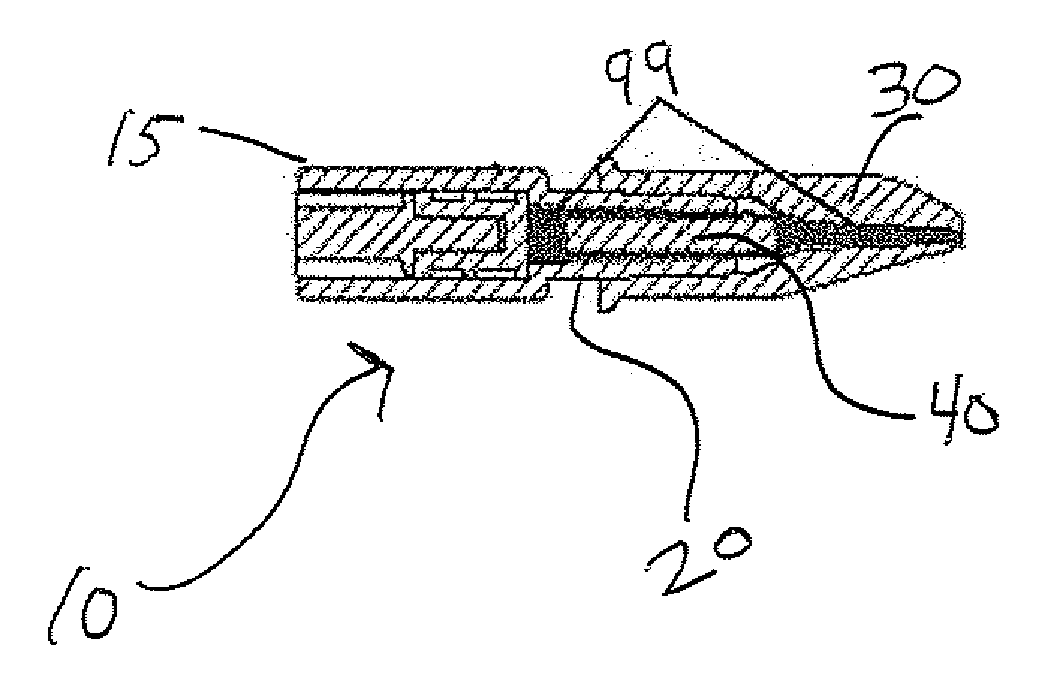
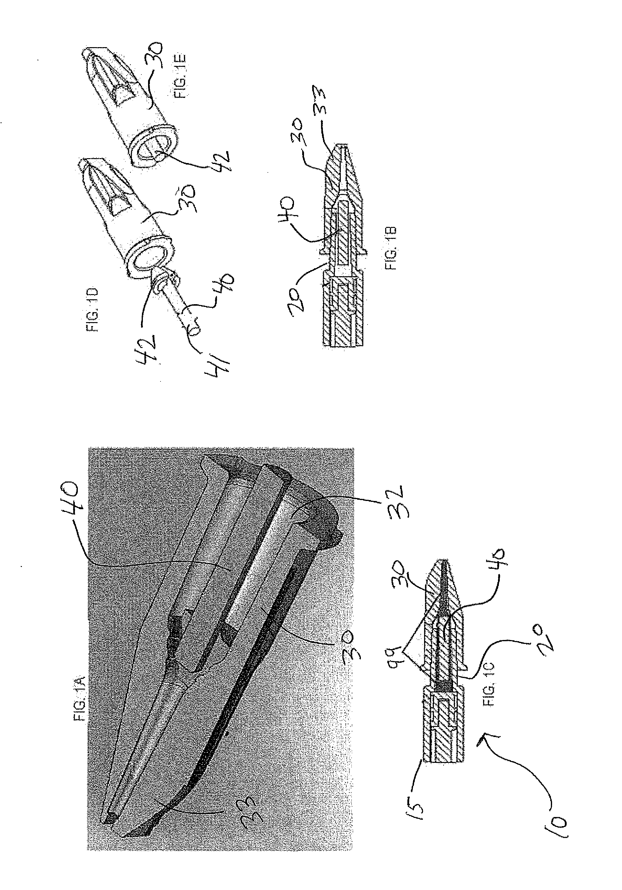
[0010]One aspect of the present invention is directed to a coupler that reduces dead space for fluids in an injection device, comprising a male fitting of an injection container; a female fitting having a proximal end for fitting inside the male fitting; and an insert disposed within the proximal end of the female fitting and disposed within the male fitting for minimizing fluid remaining in the injection container and in the female fitting after injection, the insert shaped so as to maintain a flow path between the injection container and a needle attached to the female fitting.
[0011]In a further aspect of the present invention, there is provided a coupler in an injection device, comprising a male luer-lock fitting of a syringe, a female luer-lock fitting having a proximal end for fitting inside the male luer-lock fitting; and an insert disposed within and attached to the proximal end of the female luer-lock fitting and disposed within the male luer-lock fitting for minimizing fluid remaining in the syringe and in the female luer-lock fitting after injection, the insert shaped so as to maintain a flow path between the syringe and a needle attached to the female fitting.
[0014]In a further aspect of the present invention, there is presented a microneedle injection device, comprising a disposable syringe filled with a fluid and having an aspiration needle hub at a distal end of the syringe, the aspiration needle hub having an aspiration needle projecting out of the aspiration needle hub; a microneedle hub including a septum disposed in the microneedle hub, the microneedle hub shaped to mate with the aspiration needle hub, the septum sealing a flow path between the microneedle hub and the syringe to prevent backflow of fluid into the syringe.
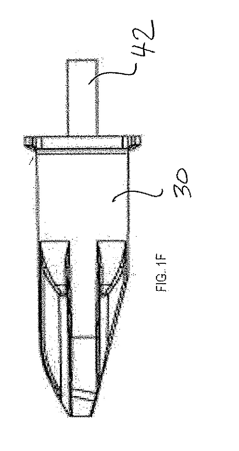
[0016]In a still further aspect of the present invention, there is presented a coupler for an injection device, comprising a male Luer-lock fitting of a syringe, the syringe not having a needle directly attached thereto; a female leer-lock fitting having a proximal end for fitting inside the male luer-lock fitting, the female leer-lock fitting also having a pipe integrally formed thereto, the pipe disposed within and extending out of a proximal end of the female luer-lock fitting, the pipe shaped to attach to the male luer-lock fitting so as to form a sealed flow path from the syringe through the male luer-lock fitting to the female luer-lock fitting that bypasses dead space in the male luer-lock fitting and in the female luer-lock fitting.
[0017]In one further aspect of the present invention, a female bier-lock fitting for a coupler of an injection device comprises a male luer-lock fitting of a syringe, the syringe not having a needle directly attached thereto; a female luer-lock fitting having a pipe integrally formed, thereto, the pipe disposed within and extending out of a proximal end of the female luer-lock fitting, the pipe shaped to attach to the male luer-lock fitting so as to form a sealed flow path from the syringe through the male luer-lock fitting to the female luer-lock fitting that bypasses dead space in the male luer-lock fitting and in the female luer-lock fitting.

Problems solved by technology

Specific structures designed on top of such glass tubes (including holders, fixed needles and shields, and injection mechanisms and devices) are not easily attached or bonded to these glass syringes because of the nature of the materials.
Drug fluids stored in pre-filled syringes may or may not be incompatible to some extent with silicon microneedle structures but in either case the compatiblity issue is sufficiently strong to trigger a need for additional testing.
This can be inconvenient and / or expensive and would require re-approval of a particular reservoir of drug fluid.
In addition to the compatibility issue, another issue arises regarding injection devices, particularly injection devices having microneedles.

Method used


Image

  • Device for injecting fluid isolated from microneedle hub with dead-space-reducing insert
  • Device for injecting fluid isolated from microneedle hub with dead-space-reducing insert
  • Device for injecting fluid isolated from microneedle hub with dead-space-reducing insert

Examples


Embodiment Construction

[0053]The following detailed description is of the best currently contemplated modes of carrying out the invention. The description is not to be taken in a limiting sense, but is made merely for the purpose of illustrating the general principles of the invention, since the scope of the invention is best defined by the appended claims.

[0054]The present invention generally provides an injection system for off-the-shelf syringes and may also have a microneedle hub having a microneedle chip. A coupler that may include an insert may be disposed in part inside a male luer lock fitting and in part inside a female luer lock fitting. The coupler may reduce dead space in both the male and female fittings. In addition, a septum may isolate the drug fluid from the microneedle chip in the hub prior to activation and the septum may, after activation, seal the triangular space in the hub to prevent leakage of fluid back to the syringe.

[0055]In contrast to the prior art, in which the residual volum...


PUM

PropertyMeasurementUnit
sizesaaaaaaaaaa
residual volumeaaaaaaaaaa

Abstract

An injection system applicable to off-the-shelf syringes having a microneedle hub may reduce dead space and isolate the drug fluid from the microneedle chip to avoid compatibility issues. An insert may be disposed inside a male luer fitting and extend so that it is also disposed inside the female luer fitting using an insert. A septum may isolate the drug fluid from the microneedle chip in the hub prior to activation and the septum may, after activation, seal the triangular space in the hub to prevent leakage of fluid back to the syringe.

Description

PRIORITY INFORMATION[0001]This patent application claims the benefit of U.S. Provisional Patent Application No. 61 / 120,865, filed Dec. 9, 2008. This patent application also claims the benefit of U.S. Provisional Patent Application No. 61 / 178,103 filed May 14, 2009.FIELD AND BACKGROUND OF THE INVENTION[0002]The present invention relates to an injection device and, more particularly, to an injection device that reduces dead space in microneedle-syringe mating arrangements and / or that safely stores the fluid apart from the microneedle chip or other needle.[0003]Applicants have previously developed an apparatus useful for shallow delivery of drug fluid through a flexible biological barrier such as the skin based on hollow and non-hollow microstructures, including microneedles, micropyramids and microprojections. For conciseness, all of these three above terms will be referred to herein generically as “microneedles” or “microneedle structures”. Furthermore, “needles” means at least one n...

Claims


Application Information

Patent Timeline
Patent Type & Authority Applications(United States)
IPC IPC(8): A61M5/31A61M5/315B32B37/00A61M5/32
CPCA61M5/1782A61M5/3202A61M5/344A61M5/347Y10T156/10A61M2005/3107A61M2005/31516A61M2005/3132A61M37/0015
Inventor AGIAN, NADAVSHEM-TOV, YONNIPANGA, BARAKSEFI, YOELLEVIN, YOTAM
Owner NANOPASS TECH LTD
Learn More