Control system of internal combustion engine

a control system and internal combustion engine technology, applied in the direction of machines/engines, process and machine control, gaseous engine fuels, etc., can solve the problems of global warming, ammonia burning does not produce cosub>2/sub>at all, and ammonia is harder to burn compared with fossil fuels

Inactive Publication Date: 2011-11-24
TOYOTA JIDOSHA KK
View PDF5 Cites 21 Cited by
  • Summary
  • Abstract
  • Description
  • Claims
  • Application Information

AI Technical Summary

Problems solved by technology

However, in this case, burning such fuels produces CO2, which causes global warming.
On the other hand, burning ammonia does not produce CO2 at all.
However, ammonia is harder to burn compared with fossil fuels.
Accordingly, the risk arises that the N2O will be discharged into the atmosphere.
Accordingly, in this case as well, there is a risk that N2O will be discharged into the atmosphere.

Method used


Image

  • Control system of internal combustion engine
  • Control system of internal combustion engine
  • Control system of internal combustion engine

Examples


first embodiment

[0042]Next, a first embodiment according to the present invention will be explained with reference to the timing chart at the time of deceleration shown in FIG. 3. Note that, in FIG. 3, the engine speed N, air-fuel ratio (A / F)g in the combustion chamber 5, air-fuel ratio (A / F)c of the exhaust gas in the exhaust purification catalyst 19, and the change of the ammonia ratio are shown.

[0043]In FIG. 3, Nc indicates a feed suspension lower limit speed. When the accelerator pedal 60 is released and deceleration is commenced, feed of the fuel is suspended if the engine speed N is higher than this feed suspension lower limit speed Nc. On the other hand, in FIG. 3, Ns indicates a resume speed. After the suspension of feed of the fuel, when the engine speed N becomes this resume speed Ns or less, feed of the fuel is restarted. Accordingly, as shown in FIG. 3, feed of the fuel is suspended during a term after the start of deceleration until when the engine speed N is lowered to the resume spee...

second embodiment

[0058]FIG. 7 shows a timing chart of a In this FIG. 7, in the same way as FIG. 3, changes of the engine speed N, air-fuel ratio (A / F)g in the combustion chamber 5, air-fuel ratio (A / F)c of the exhaust gas in the exhaust purification catalyst 19, and the ammonia ratio are shown.

[0059]As will be understood from FIG. 7, in this second embodiment, at the time when feed of the fuel is restarted after suspension of feed of the fuel at the time of deceleration, the air-fuel ratio (A / F)g is temporarily made rich. Namely, in this second embodiment, as shown in FIG. 7, the air-fuel ratio is made rich during the period where the air-fuel ratio (A / F)c of the exhaust gas flowing out from the exhaust purification catalyst 19 is lean after the restart of the feed of the fuel. In this way, when the air-fuel ratio is made rich, the time during which the exhaust purification catalyst 19 exhibits a lean state can be made short, and thus discharge of N2O into the atmosphere can be suppressed.

[0060]Fur...

third embodiment

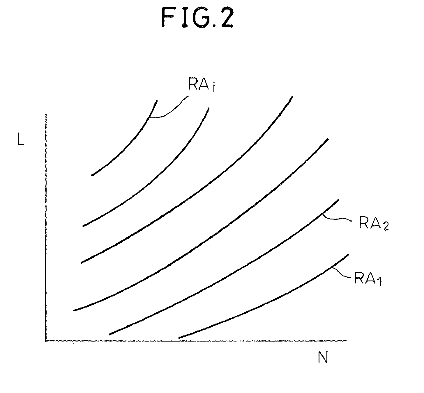
[0072]FIG. 12 shows a fuel injection control routine for executing a Referring to FIG. 12, first of all, at step 100, the basic ammonia ratio RA is calculated from the map shown in FIG. 2. Next, at step 101, the target air-fuel ratio (A / F)t is calculated. In this embodiment as well, this target air-fuel ratio (A / F)t is set to the stoichiometric air-fuel ratio. Next, at step 102, the temperature TC of the exhaust purification catalyst 19 detected by the temperature sensor 41 is read. Next, at step 103, the reduction ΔR of ammonia is calculated from the relationship shown in FIG. 11.

[0073]Next, at step 104, the reference ammonia ratio RA is reduced by the reduction ΔR. Namely, if ΔR>0 at this time, the ammonia ratio RA targeted is lowered. Next, at step 105, the intake air amount detected by the intake air amount detector 17 is read. Next, at step 106, the amount of ammonia to be injected from the ammonia injector 13 and the amount of the second fuel to be injected from the fuel inje...


PUM


Abstract

A control system of an internal combustion engine in which a first fuel of ammonia and a second fuel which is easier to burn than ammonia are used as fuels. An ammonia ratio is usually set to a reference ammonia ratio which is determined in advance in accordance with an operating state of an engine. At the time when feed of the fuel is restarted after suspension of feed of the fuel at the time of deceleration, the ammonia ratio is temporarily made lower than the reference ammonia ratio in accordance with the operating state of the engine.

Description

BACKGROUND OF THE INVENTION[0001]1. Field of the Invention[0002]The present invention relates to a control system of an internal combustion engine.[0003]2. Description of the Related Art[0004]In an internal combustion engine, in the past, the fuel used has mainly been fossil fuels. However, in this case, burning such fuels produces CO2, which causes global warming. On the other hand, burning ammonia does not produce CO2 at all. Thus, there is known an internal combustion engine made so as to use ammonia as fuel and not produce CO2 (for example, see Japanese Patent Publication (A) No. 5-332152.).[0005]However, ammonia is harder to burn compared with fossil fuels. Therefore, when using ammonia as fuel, some sort of measure is required for making the ammonia easier to burn. Thus, in the above-mentioned internal combustion engine, exhaust heat is utilized to reform the ammonia so as to produce reformed gas comprised of hydrogen and nitrogen, the hydrogen in the produced reformed gas is ...

Claims


Application Information

Patent Timeline
Patent Type & Authority Applications(United States)
IPC IPC(8): F02D41/00F02D41/30F01N3/02F23C1/00
CPCF01N3/043F01N3/30F01N2240/30F01N2560/025F01N2560/06F01N2570/18F01N13/009F02D41/123F02D41/126F02D41/3005F02M25/10F02M43/00Y02T10/20F02D41/0025F01N5/02F02D19/0644F02D19/0671F02D19/08F01N2430/06F01N2430/085Y02T10/12Y02T10/30
Inventor ASO, KOJIFUJIWARA, TAKAHIKOTANAKA, HIROSHI
Owner TOYOTA JIDOSHA KK
Why Eureka
Try Eureka