Semiconductor devices including gate structure and method of fabricating the same

a technology of semiconductor devices and gate structures, applied in the direction of semiconductor devices, basic electric elements, electrical appliances, etc., can solve the problems of scaled down performance degradation, and achieve the effect of less thickness, less thickness, and less thickness

Active Publication Date: 2011-11-24
SAMSUNG ELECTRONICS CO LTD
View PDF4 Cites 45 Cited by
  • Summary
  • Abstract
  • Description
  • Claims
  • Application Information

AI Technical Summary

Benefits of technology

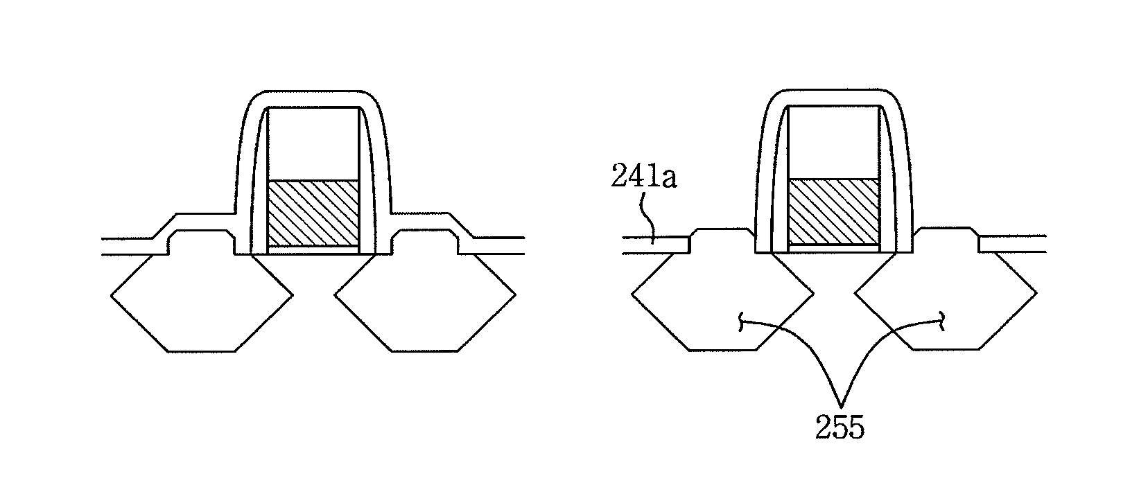
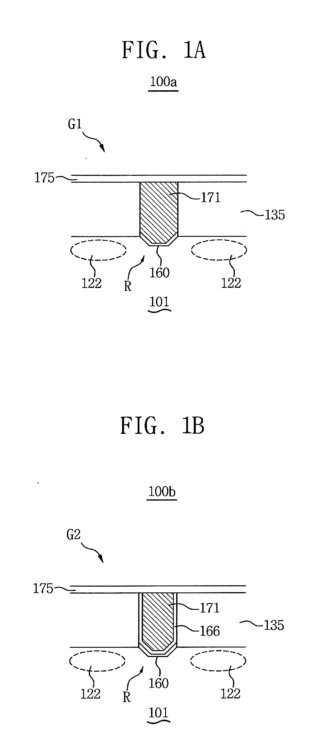
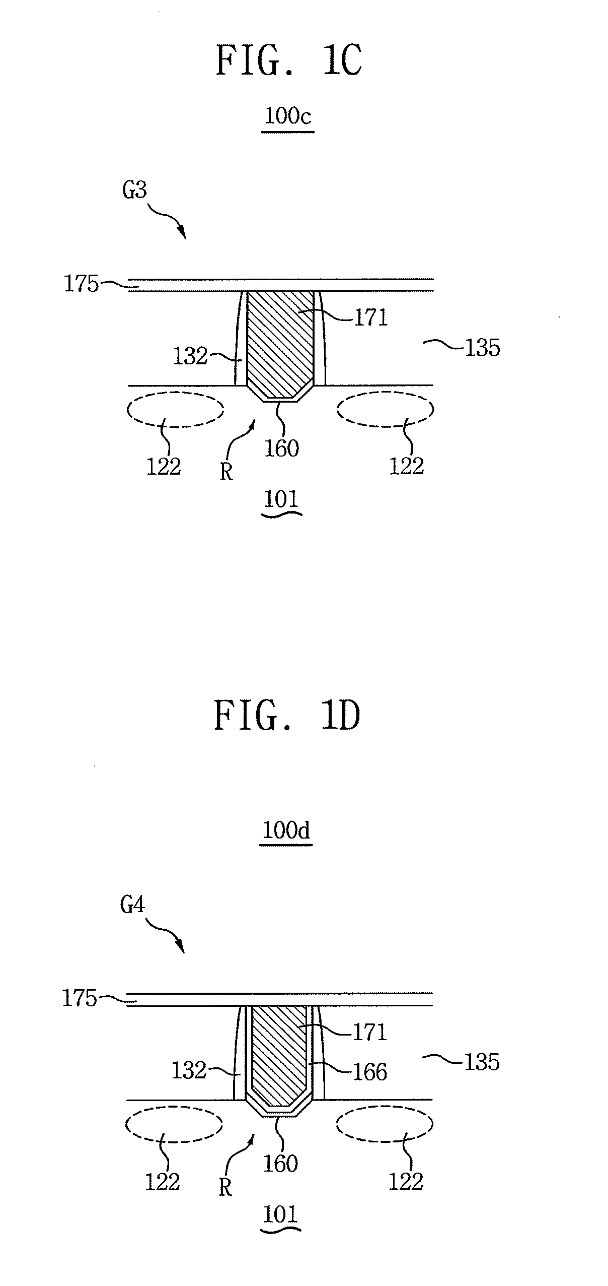
[0006]In accordance with an aspect of the inventive concept, a semiconductor device comprises a semiconductor substrate having a top surface and a recessed portion including at least two oblique side surfaces and a first bottom surface therebetween, a gate insulating layer formed on the recessed portion, a gate electrode formed on the gate insulating layer, a channel region below the gate electrode in the semiconductor substrate; and gate spacers formed on side surfaces of the gate electrode, wherein both the bottom surface and the side surfaces of the recessed portion include flat surfaces. The top surface of the semiconductor has a {100}, {010}, {001}, {110}, {101}, or {011} crystal orientation, and the at least two side surfaces have a {111} crystal orientation. The gate insulating layer has less thickness on the bottom surface than those on the side surfaces. The semiconductor substrate further includes a first embedded source / drain region, a second embedded source / drain region, and a channel region disposed between the first and second embedded source / drain regions. The first embedded source / drain region comprises a first upper side surface, a first lower surface and a first intersection line between the first upper and lower surfaces, and the second embedded source / drain region comprises a second upper side surface, a second lower surface and a second intersection line between the second upper and lower surfaces. The first embedded source / drain region is distant from the second embedded source / drain region at a shortest distance between the first and second intersection lines. The first and second intersection lines run along and adjoin the channel region. An intersection angle between the first upper and lower side surfaces is less than 90 degree. The first embedded source / drain region is formed of epitaxially grown SiGe or SiC. Each of the upper and lower surfaces of the first embedded source / drain region comprises a flat surface of {111} crystal orientation.
[0007]In accordance with another aspect of the inventive concept, the gate insulating layer includes a first gate insulating layer on the recessed portion and a second gate insulating layer formed on the first gate insulating layer, wherein the first gate insulating layer has less thickness on the bottom surface than those on the side surfaces. The first gate insulating layer is formed of silicon oxide, and the second gate insulating layer is formed of an insulating material having a higher dielectric constant than that of the first gate insulating layer.
[0008]In accordance with an aspect of the inventive concept, a method of manufacturing a semiconductor device comprising the steps of forming a recess portion including at least two oblique side surfaces and a bottom surface therebetween in a semiconductor substrate, forming a gate insulating layer formed on the recessed portion, forming a gate electrode formed on the gate insulating layer, forming a channel region below the gate electrode in the semiconductor substrate, and forming gate spacers formed on side surfaces of the gate electrode. The step of forming a recess portion has a resultant side surfaces of a {111} crystal orientation. The step of forming a gate insulating layer has a resultant the gate insulating layer having less thickness on the bottom surface than those on the side surfaces. The step of forming a gate insulation layer includes a step of forming a first gate insulation layer and a step of forming a second gate insulation layer, the first gate insulation layer being formed of silicon dioxide and having less thickness on the bottom surface than those on the side surface, and the second gate insulation layer being formed of an insulating material having a higher dielectric constant than that of the first gate insulating layer. 17. The method of claim 13, further comprising the step of forming a patterned hard etch mask. Dry etching is performed to form a trench in the semiconductor substrate and wet etching is sequentially performed to form a bracket shape on sidewalls of the trench, wherein the bracket shape trench includes a upper flat surface and a lower flat surface and further includes an intersection line between the upper and lower flat surface, the intersection line running along and adjoining the channel region. The bracket shaped trench is filled by selectively growing epitaxial layer. The epitaxial layer is SiGe or SiC.

Problems solved by technology

As a semiconductor device is highly integrated, degradation in performance caused by scaled down has been on the rise, and continuous efforts to prevent deteriorated performance or improve performance have been made.

Method used


Image

  • Semiconductor devices including gate structure and method of fabricating the same
  • Semiconductor devices including gate structure and method of fabricating the same
  • Semiconductor devices including gate structure and method of fabricating the same

Examples


Embodiment Construction

[0018]Various embodiments will now be described more fully with reference to the accompanying drawings in which some embodiments are shown. These inventive concepts may, however, be embodied in different forms and should not be construed as limited to the embodiments set forth herein. Rather, these embodiments are provided so that this disclosure is thorough and complete and fully conveys the inventive concept to those skilled in the art. In the drawings, the sizes and relative sizes of layers and regions may be exaggerated for clarity.

[0019]It will be understood that when an element or layer is referred to as being “on,”“connected to” or “coupled to” another element or layer, it can be directly on, connected or coupled to the other element or layer or intervening elements or layers may be present. In contrast, when an element is referred to as being “directly on,”“directly connected to” or “directly coupled to” another element or layer, there are no intervening elements or layers p...


PUM


Abstract

A semiconductor device includes a semiconductor substrate having a top surface and a recessed portion including at least two oblique side surfaces and a first bottom surface therebetween, a gate insulating layer formed on the recessed portion, a gate electrode formed on the gate insulating layer, a channel region below the gate electrode in the semiconductor substrate, and gate spacers formed on side surfaces of the gate electrode, wherein both the bottom surface and the side surfaces of the recessed portion include flat surfaces. A method of manufacturing a semiconductor device comprising the steps of forming a recess portion including at least two oblique side surfaces and a bottom surface therebetween in a semiconductor substrate, forming a gate insulating layer formed on the recessed portion, forming a gate electrode formed on the gate insulating layer, forming a channel region below the gate electrode in the semiconductor substrate, and forming gate spacers formed on side surfaces of the gate electrode.

Description

CROSS-REFERENCE TO RELATED APPLICATION[0001]This application claims priority under 35 U.S.C. §119 to Korean Patent Application No. 10-2010-47063 filed on May 19, 2010, the disclosure of which is hereby incorporated by reference in its entirety.BACKGROUND[0002]1. Field[0003]Embodiments of the inventive concept relate to semiconductor devices including a gate structure and methods of fabricating the same.[0004]2. Description of Related Art[0005]As a semiconductor device is highly integrated, degradation in performance caused by scaled down has been on the rise, and continuous efforts to prevent deteriorated performance or improve performance have been made.SUMMARY[0006]In accordance with an aspect of the inventive concept, a semiconductor device comprises a semiconductor substrate having a top surface and a recessed portion including at least two oblique side surfaces and a first bottom surface therebetween, a gate insulating layer formed on the recessed portion, a gate electrode form...

Claims


Application Information

Patent Timeline
Patent Type & Authority Applications(United States)
IPC IPC(8): H01L29/772
CPCH01L29/66545H01L29/66636H01L29/66628H01L29/66621H01L29/165H01L29/7848H01L29/4232
Inventor LEE, KWANG-WOOKBAEK, JAE-JIKHWANG, IN-SEAKNAM, SEOK-WOO
Owner SAMSUNG ELECTRONICS CO LTD
Why Eureka
Try Eureka