Stylus and electronic device

a stylus and electronic device technology, applied in the field of electronic devices, can solve the problems of increasing the manufacturing cost, the limited area of the touch display screen 114, and the increase of the number of components, so as to achieve the effect of reducing the manufacturing cost and increasing the area of the whole display fram

Inactive Publication Date: 2011-11-24
UNIHAN CORPORATION
View PDF14 Cites 24 Cited by
  • Summary
  • Abstract
  • Description
  • Claims
  • Application Information

AI Technical Summary

Benefits of technology

[0018]According to the above, the electronic device in the invention includes a stylus with a movable element. A user can allow the electronic device to generate a corresponding action by rotating or sliding the movable element, such as turning over a page of the display frame presented by the electronic device or controlling the page to move, roll, or return. In addition, since the electronic device can achieve the operation such as moving upward, downward, leftward, or rightward or returning via the stylus, the number of the components (such as the direction key) and the molding cost can be reduced, and the area of the whole display frame can be increased.

Problems solved by technology

However, an area of the touch display screen 114 may be limited correspondingly.
In addition, since keys such as the direction key 112 are needed, the number of components and the whole manufacturing cost may increase.

Method used


Image

  • Stylus and electronic device
  • Stylus and electronic device
  • Stylus and electronic device

Examples


Embodiment Construction

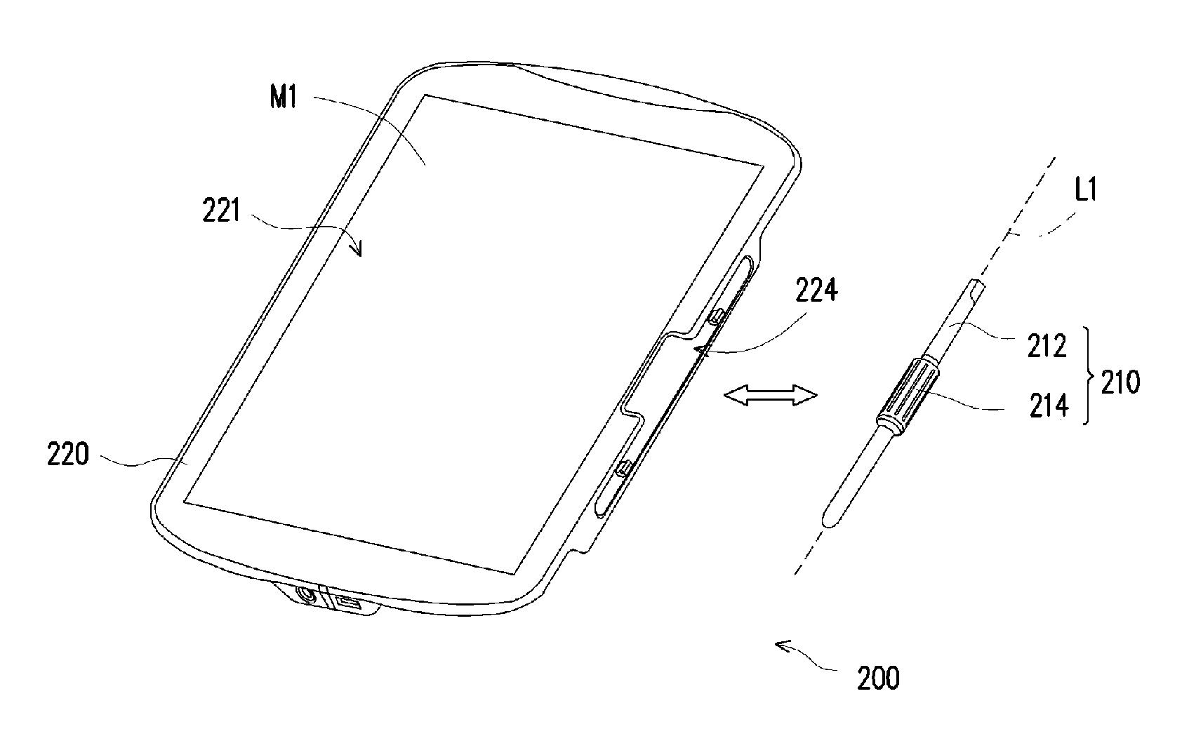
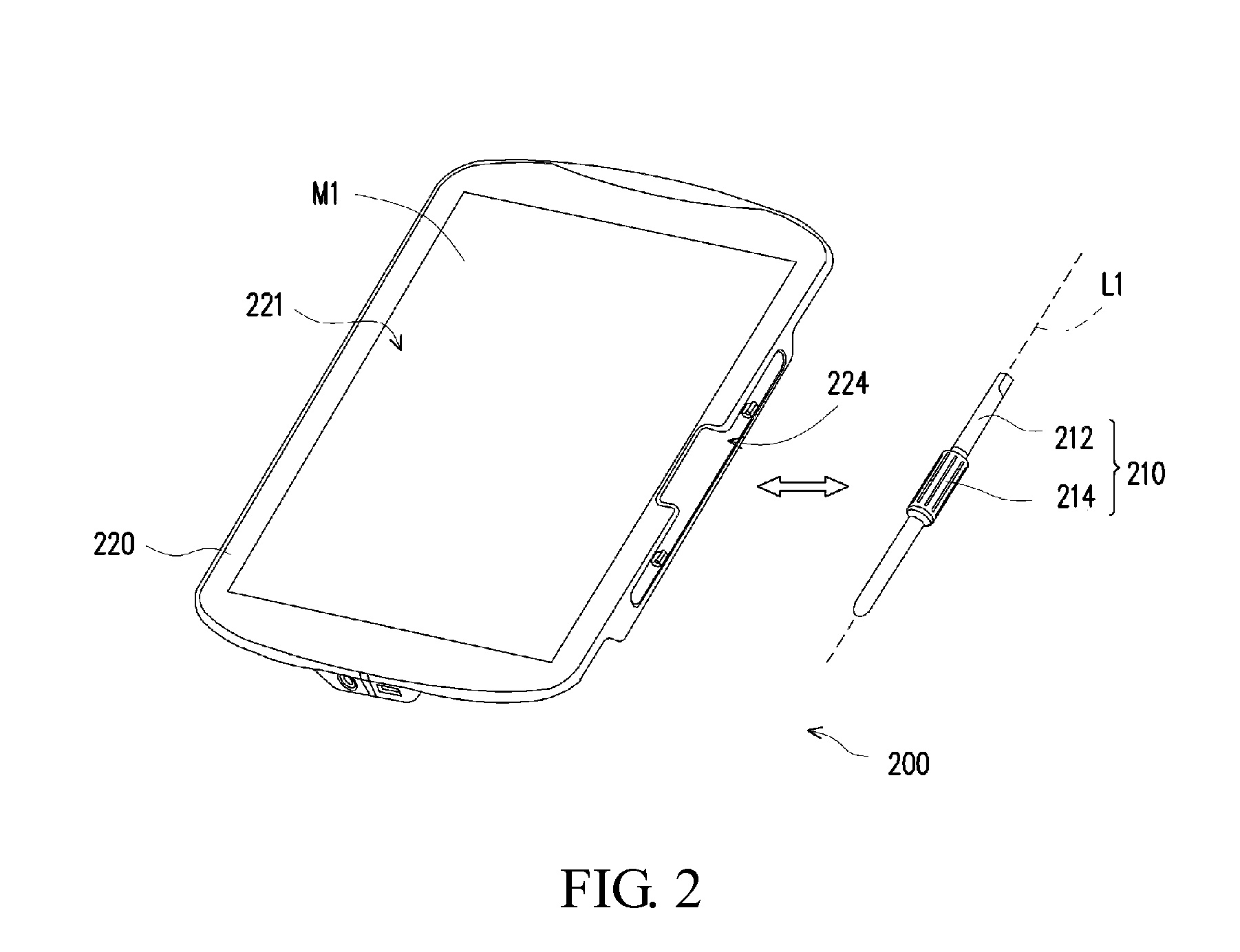
[0024]FIG. 2 is a schematic diagram showing an electronic device according to one embodiment of the invention. FIG. 3 is a partial perspective diagram showing operation of a stylus when the stylus is installed in a main body in the electronic device in FIG. 2. In FIG. 2 and FIG. 3, an electronic device 200 in the embodiment includes a stylus 210 and a main body 220. The stylus 210 is detachably connected with the main body 220 and includes a penholder 212 and a movable element 214. The movable element 214 is disposed at the penholder 212 and allowed to pivot around or slide along the penholder 212 which is used as an axis L1. In the embodiment, the movable element 214 may be fastened to the penholder 212. Thus, when the movable element 214 pivots around the axis L1 or slides along the axis L1, the movable element 214 can drive the penholder 212 to pivot or slide together. In other words, according to design and needs of users, the movable element 214 and the penholder 212 may be int...


PUM


Abstract

This invention provides a stylus and an electronic device. The electronic device includes a stylus and a main body. The main body includes a display screen and at least one sensing element. The stylus is detachably connected with the main body. The stylus includes a penholder and a movable element. The movable element is disposed at the penholder and allowed to pivot around or slide along the penholder which is used as an axis. The sensing element senses the pivoting or sliding of the movable element to generate a control signal. The main body controls a display frame of the display screen according to the control signal.

Description

CROSS-REFERENCE TO RELATED APPLICATIONS[0001]This Non-provisional application claims priority under 35 U.S.C. §119(a) on Patent Application No(s). 099116503 filed in Taiwan, Republic of China on May 24, 2010, the entire contents of which are hereby incorporated by reference.BACKGROUND OF THE INVENTION[0002]1. Field of the Invention[0003]This invention relates to an electronic device and, more particularly, to an electronic device with a stylus.[0004]2. Description of the Related Art[0005]FIG. 1 is a schematic diagram showing a conventional electronic device. In FIG. 1, an electronic device 100 includes a main unit 110 and a stylus 120. The main unit 110 includes a direction key 112 and a touch display screen 114. The stylus 120 is used for touching the touch display screen 114 of the main unit 110 for selection or operation. In addition, the direction key 112 can be used for browsing a page presented on the touch display screen 114 or be used for operating a figure of a frame presen...

Claims


Application Information

Patent Timeline
Patent Type & Authority Applications(United States)
IPC IPC(8): G06F3/033G09G5/00
CPCG06F1/1626G06F2200/1632G06F3/0362G06F3/03545G06F3/0487
Inventor WU, CHIA-HSIENCHANG, CHIA-WEICHENG, WEN-CHUNG
Owner UNIHAN CORPORATION
Why Eureka
Try Eureka