Bone Anchors

a technology of bone anchors and bones, applied in the field of bone anchors, can solve the problems of pulling out or otherwise displaced bone anchors, and achieve the effect of improving bone anchor assemblies

Inactive Publication Date: 2011-11-24
DEPUY SYNTHES PROD INC
View PDF13 Cites 140 Cited by
  • Summary
  • Abstract
  • Description
  • Claims
  • Application Information

AI Technical Summary

Benefits of technology

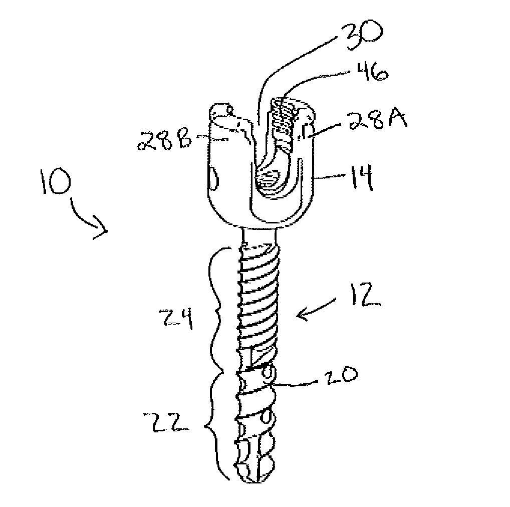
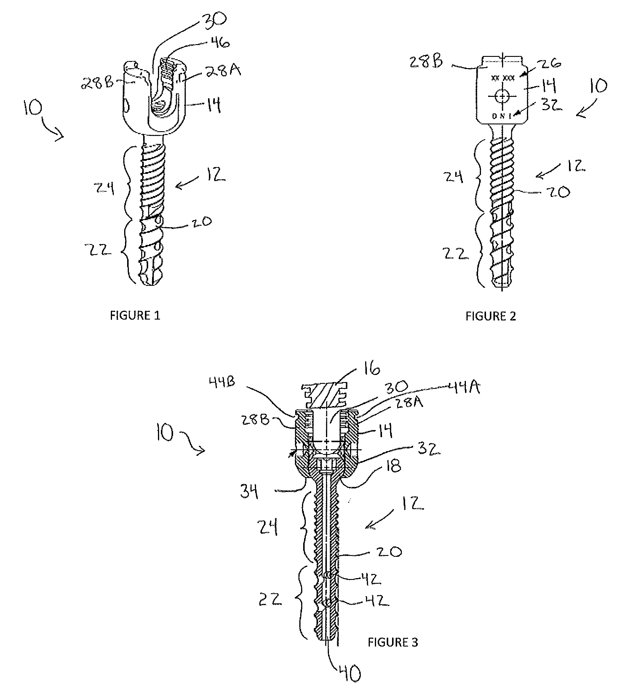
Disclosed herein are improved bone anchor assemblies and, in particular, improved bone anchor assemblies used in connection with spinal fixation elements to fix multiple vertebrae either rigidly or dynamically.
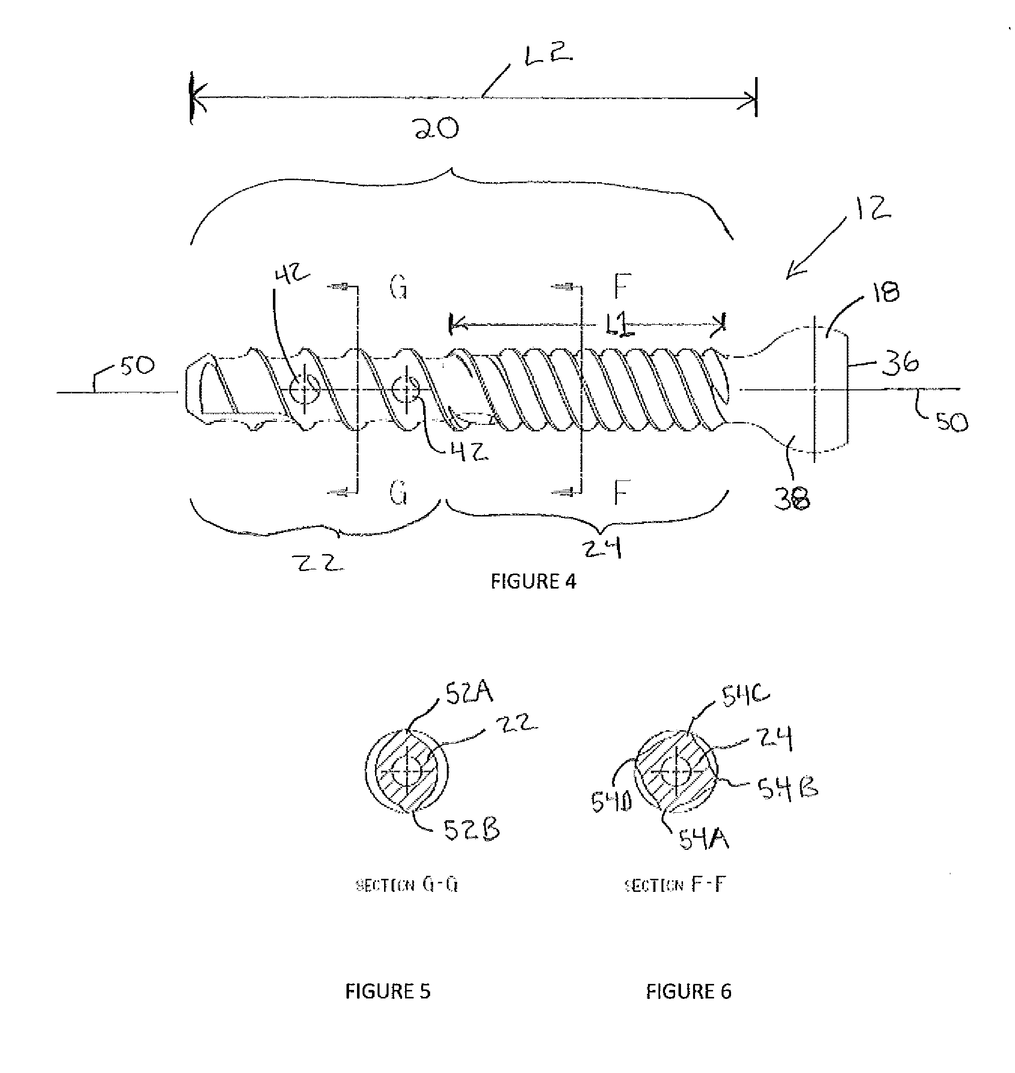
In accordance with one aspect, a bone anchor assembly may include a bone anchor, a receiver member for receiving a spinal fixation element to be coupled to the bone anchor, and a closure mechanism to capture a spinal fixation element within the receiver member and fix the spinal fixation element with respect to the receiver member. The bone anchor may have a proximal head and a distal shaft configured to engage bone. The distal shaft may include a distal threaded section and a proximal threaded section. The distal threaded section may have a

Problems solved by technology

One problem with the use of bone anchors is that bone anchors may pullout or otherwise be displaced from the bone prior to the healing or fu

Method used


Image

  • Bone Anchors
  • Bone Anchors
  • Bone Anchors

Examples


Embodiment Construction

Certain exemplary embodiments will now be described to provide an overall understanding of the principles of the structure, function, manufacture, and use of the devices and methods disclosed herein. One or more examples of these embodiments are illustrated in the accompanying drawings. Those of ordinary skill in the art will understand that the devices and methods specifically described herein and illustrated in the accompanying drawings are non-limiting exemplary embodiments and that the scope of the present invention is defined solely by the claims. The features illustrated or described in connection with one exemplary embodiment may be combined with the features of other embodiments. Such modifications and variations are intended to be included within the scope of the present invention.

The articles “a” and “an” are used herein to refer to one or to more than one (i.e. to at least one) of the grammatical object of the article. By way of example, “an element” means one element or ...


PUM


Abstract

A bone anchor assembly includes a bone anchor, a receiver member for receiving a spinal fixation element to be coupled to the bone anchor, and a closure mechanism to fix the spinal fixation element with respect to the receiver member. The bone anchor includes a distal shaft having a distal threaded section and a proximal threaded section. The distal threaded section has a first pitch and a first number of thread starts and the proximal threaded section has a second pitch less than the first pitch and a second number of thread starts greater than the first number of thread starts. The distal threaded section and the proximal threaded section have a constant lead.

Description

BACKGROUNDBone anchors may be used in orthopedic surgery to fix bone during the healing or fusion process. In spinal surgery, bone anchors may be used with spinal fixation elements, such as spinal rods, to stabilize multiple vertebrae either rigidly, in which no relative motion between the vertebrae is desired, and dynamically, in which limited, controlled motion between the vertebrae is desired. One problem with the use of bone anchors is that bone anchors may pullout or otherwise be displaced from the bone prior to the healing or fusion process completing. This problem is particularly common when a bone anchor is positioned in poor quality bone such as osteoporotic bone. Accordingly, there is need for improved bone anchors that minimize instances of anchor pull out.SUMMARYDisclosed herein are improved bone anchor assemblies and, in particular, improved bone anchor assemblies used in connection with spinal fixation elements to fix multiple vertebrae either rigidly or dynamically.In...

Claims


Application Information

Patent Timeline
IPC IPC(8): A61B17/86
CPCA61B17/7037A61B17/863A61B17/864
Inventor MICHIELLI, MICHAELJONES, BRYAN S.CORMIER, PHILIPSERHAN, HASSAN
Owner DEPUY SYNTHES PROD INC
Why Eureka
Try Eureka