Neurostimulation lead anchors

Inactive Publication Date: 2011-11-24
BOSTON SCI NEUROMODULATION CORP
View PDF14 Cites 17 Cited by
  • Summary
  • Abstract
  • Description
  • Claims
  • Application Information

AI Technical Summary

Benefits of technology

[0020]If each anchoring element further includes a barb element located on the respective spike, it may resist removal of the anchoring element from the solid tissue. The barb element(s) may break off from the spike by removing the anchoring element from the solid tissue. In the case where each spike includes a sheath and a stem carrying the barb element(s), the s

Problems solved by technology

This process, however, is time consuming and difficult for less experienced surgeons or anesthesiologists to effe

Method used


Image

  • Neurostimulation lead anchors
  • Neurostimulation lead anchors
  • Neurostimulation lead anchors

Examples


Embodiment Construction

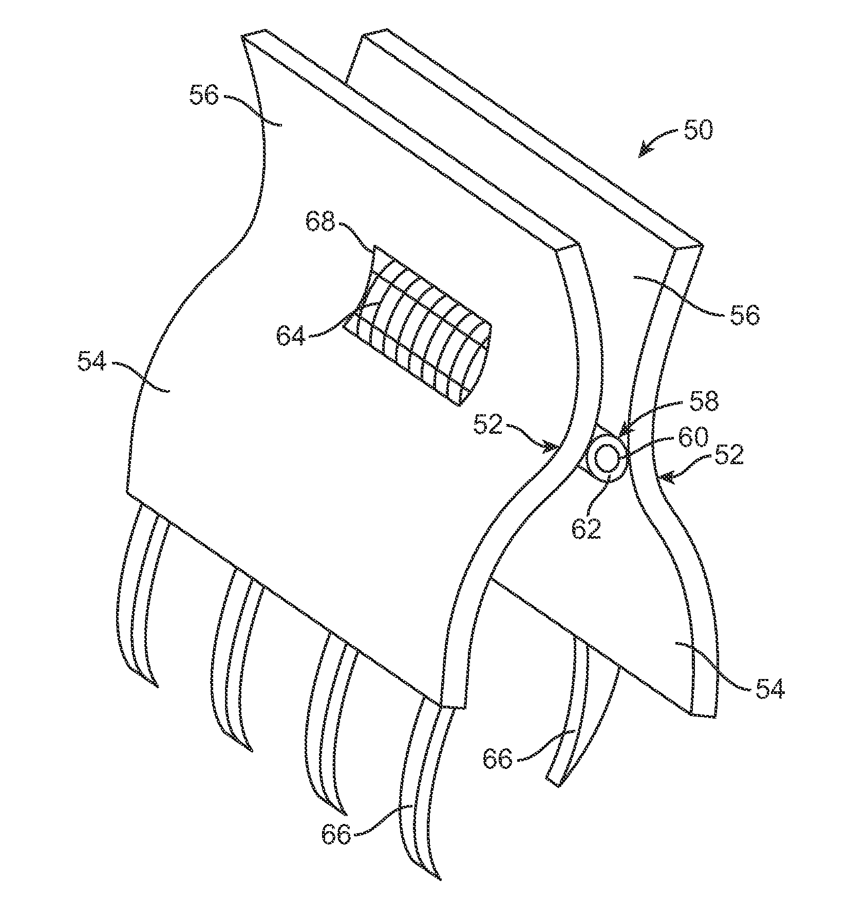
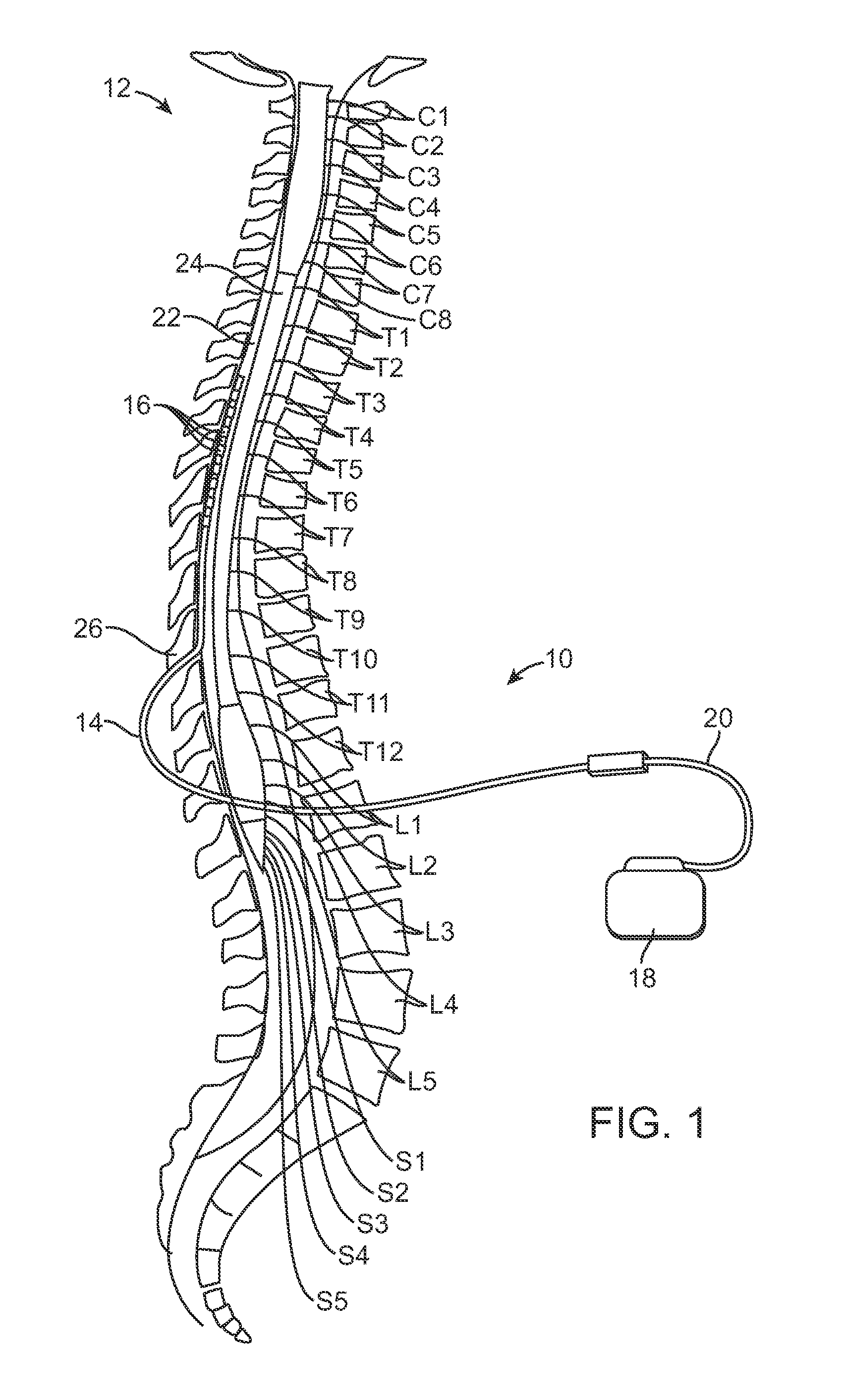
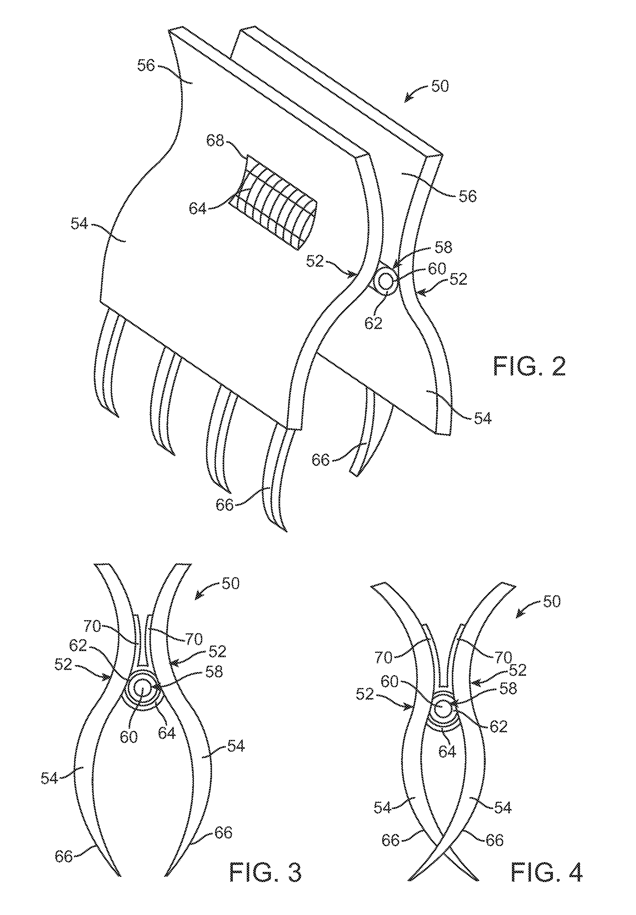
[0045]At the outset, it should be noted that the present invention is directed to the fixation of implantable leads, such as neural stimulation leads or cardiac leads, and more particularly to the fixation of electrodes or electrode arrays attached to the neural stimulation leads or cardiac leads, so that such electrodes or electrode arrays remain in a desired position relative to the tissue that is to be stimulated. It should further be noted that the principles and teachings of the invention may be used with any kind of neural stimulation lead, cardiac lead, or catheter, particularly those that are implanted within a tissue cavity (the presence of which cavity allows undesirable movement of the lead). For the purposes of this specification, a “lead” will be considered as any elongated medical device designed to be implanted and affixed within a patient's body. Thus, while the invention will be described in terms of a spinal cord stimulation (SCS) lead adapted for implantation in t...


PUM


Abstract

In accordance with the present inventions, anchoring devices for a lead (e.g., a neurostimulation lead) placed on solid tissue (e.g., fascia) and methods of anchoring the lead relative to the tissue are provided. Such methods may include inserting the lead into an epidural space and coupling the lead to a neurostimulation.

Description

RELATED APPLICATION[0001]The present application claims the benefit under 35 U.S.C. §119 to U.S. provisional patent application Ser. No. 61 / 346,665, filed May 20, 2010. The foregoing application is hereby incorporated by reference into the present application in its entirety.FIELD OF THE INVENTION[0002]The present invention relates to tissue stimulation systems, and more particularly, to devices for anchoring implanted neurostimulation leads relative to the surrounding tissue.BACKGROUND OF THE INVENTION[0003]Implantable neurostimulation systems have proven therapeutic in a wide variety of diseases and disorders. Pacemakers and Implantable Cardiac Defibrillators (ICDs) have proven highly effective in the treatment of a number of cardiac conditions (e.g., arrhythmias). Spinal Cord Stimulation (SCS) systems have long been accepted as a therapeutic modality for the treatment of chronic pain syndromes, and the application of tissue stimulation has begun to expand to additional applicatio...

Claims


Application Information

Patent Timeline
IPC IPC(8): A61N1/05
CPCA61N1/0558A61N1/0551
Inventor GLEN, KEVIN ALANACKERMANN, DOUGLAS MICHAELCHEN, ROGER
Owner BOSTON SCI NEUROMODULATION CORP
Why Eureka
Try Eureka