
Container for temporarily holding water on the roof of a building with a controlled leakage rate

a technology for storing containers and roofs, applied in drinking water installation, roof improvement, gas/liquid distribution and storage, etc., can solve the problems of increasing the risk of flooding, and increasing the cost of collection, so as to reduce the leakage rate and control the effect of the leakage ra

Inactive Publication Date: 2011-12-01
LAME RAPHAEL +1
View PDF11 Cites 11 Cited by
  • Summary
  • Abstract
  • Description
  • Claims
  • Application Information

AI Technical Summary

Benefits of technology

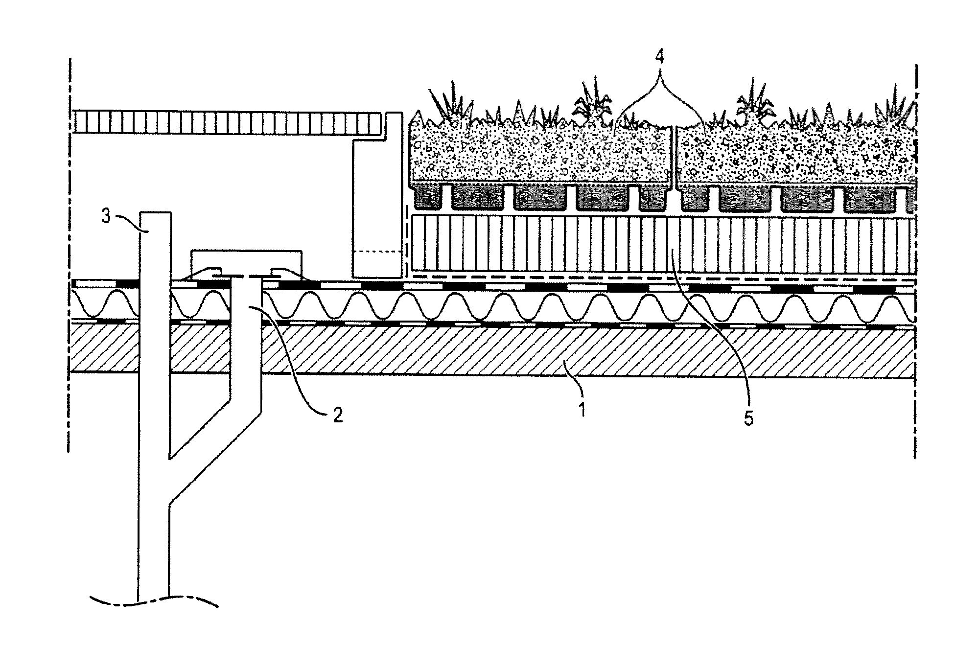
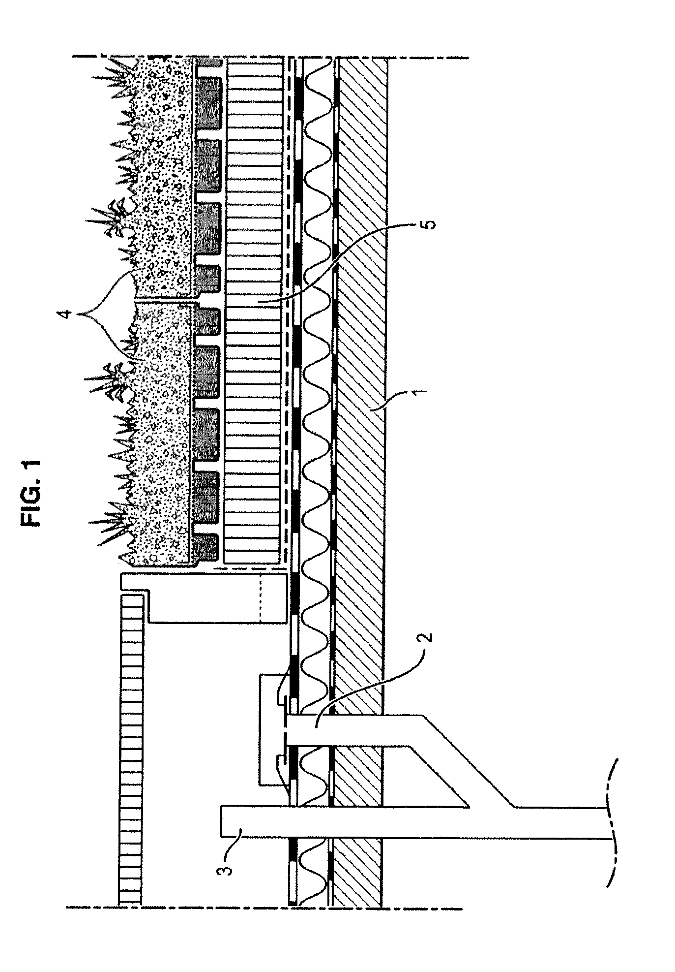
The objective of the invention is in particular to make it possible to temporarily retain rainwater on roofs having a slope in order to reduce and control the leakage rate thereof.

Problems solved by technology

Because of the increasing rain-proofing of urban ground and roofs, the management of rainwater is becoming a major problem.
This collection has a financial cost (pipes, retention basins, water treatment plants), and an ecological cost since the water is soiled by numerous pollutants on its travel (waste, hydrocarbons, heavy metals, etc.).
In addition, a second problem related to the rain-proofing of ground is the increase risk of flooding.
During violent storms, greater and greater volumes of rainwater run off, giving rise to a saturation of sewers and overflowing.
Planted roofs therefore reduce the rain-proofing coefficient of the surfaces.
The current systems on planted roofs do however have certain limitations.
In addition, though planted roofs reduce the annual mean run-off coefficient by approximately 50%, they do not provide systematic reduction of each rainy event.
However, the model of storing roofs cannot at present find application except for roofs with a zero slope.

Method used


Image

  • Container for temporarily holding water on the roof of a building with a controlled leakage rate
  • Container for temporarily holding water on the roof of a building with a controlled leakage rate
  • Container for temporarily holding water on the roof of a building with a controlled leakage rate

Examples


first embodiment

shown in FIGS. 3a and 3b, the obturator 32 is rotated in front of the orifice 14. The obturator is for example in the form of a portion of a disc 32 in which a slot 31 with progressive opening is formed. This progressive opening ensures a constant leakage rate when the temporary volume of water decreases or increases by rotating the disc 32 and therefore modifying the position of the slot in front of the orifice.

In a variant, it is possible to provide, in place a slot formed in a disc portion, a blade the thickness of which varies progressively in order to ensure a constant leakage rate when the blade closes off the opening.

With reference to FIG. 3a, the orifice 14 is formed through the wall of the container close to the bottom 11 of the container. The progressive-opening slot 31 is formed in a disc 32 mounted so as to rotate about the rotation spindle 33 perpendicular to the wall. The disc is connected to the float 30 via the arm 34 pivoting about the spindle 33, so as to pivot aga...

second embodiment

shown in FIGS. 4a-4b and FIGS. 5a-5b, the obturator 37, 38 is rotated about a spindle 33 through the orifice 14.

The obturator for example takes the form of a horn 37, 38 associated with an arm 34 pivoting about the spindle 33 under the action of a float 30 to which it is connected. The horn, the diameter of which increases progressively, thus adjusts the opening of the orifice according to the volume of water remaining to be drained in the container. The orifice can be formed in the bottom of the container (FIGS. 4a-4b) or through a wall of the container (FIGS. 5a-5b), which creates a residual volume of water 42.

In the variant shown in FIGS. 6a-6b, the means of discharging water with a constant leakage rate comprise an obturator 43 directly driven by a float 30 in translation through the orifice 14.

The obturator is for example formed by a cone 43, at the head of which a float 30 is provided. The orifice 14 is here formed in the bottom of the container, while the cross-section of the...


PUM


Abstract

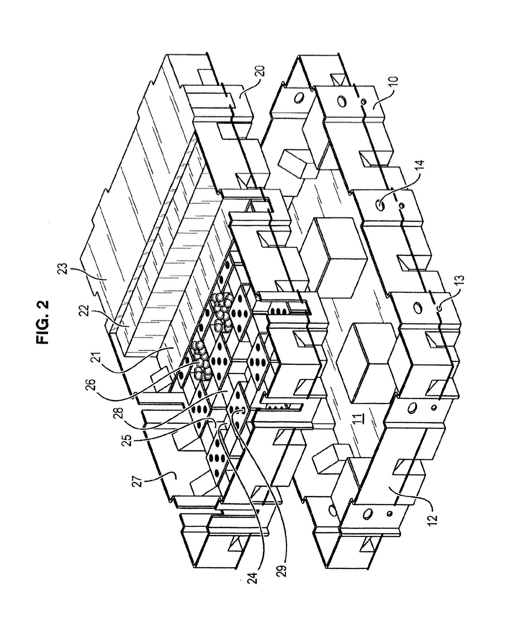
According to a first aspect, the invention relates to a container (10) for temporarily holding water on the roof of a building, including a bottom (11), a side wall (12) surrounding the bottom (11) and an overflow opening (14) for draining surplus water when the volume of water collected in the container (10) exceeds a buffer volume, characterised in that the container (10) includes a water-draining means configured to force water with a temporary storage volume which is lower than the buffer volume to flow according to a regulated leakage rate (13), and in that the dimensions of the bottom are smaller than the dimensions of a sloping roof on which the container (10) can be placed so that the water load is distributed evenly on the surface of the roof when a plurality of containers (10) of the same size cover the surface of the roof.

Description

FIELD OF THE INVENTIONThe field of the invention is that of the management of rainwater.The invention concerns more precisely a device for controlling the discharge of rainwater on roofs, in particular on sloping roofs.BACKGROUND OF THE INVENTIONBecause of the increasing rain-proofing of urban ground and roofs, the management of rainwater is becoming a major problem.This is because the water cannot infiltrate into rain-proofed ground or on roofs. A major part of the rainwater must therefore be collected and treated. This collection has a financial cost (pipes, retention basins, water treatment plants), and an ecological cost since the water is soiled by numerous pollutants on its travel (waste, hydrocarbons, heavy metals, etc.).In addition, a second problem related to the rain-proofing of ground is the increase risk of flooding. During violent storms, greater and greater volumes of rainwater run off, giving rise to a saturation of sewers and overflowing.Planted roofs afford concrete...

Claims


Application Information

Patent Timeline
Patent Type & Authority Applications(United States)
IPC IPC(8): E03B3/03E03B11/12E03B11/00
CPCE04D11/002A01G1/007Y02B80/32A01G9/033Y10T137/6969Y10T137/7039Y10T137/86187Y10T137/86236Y10T137/86252Y02A30/254
Inventor LAME, RAPHAELREDJALA-OUNNAS, TANEGMART
Owner LAME RAPHAEL
Learn More