System and method for using a mobile electronic device to optimize an energy management system

a technology of energy management system and electronic device, which is applied in the field of system and method for optimizing an energy management system, can solve the problems of inability to take into account more than two devices, the cost of the device, and the general user interface of the programmable thermosta

Active Publication Date: 2011-12-01
ECOFACTOR
View PDF2 Cites 304 Cited by
  • Summary
  • Abstract
  • Description
  • Claims
  • Application Information

AI Technical Summary

Benefits of technology

In one embodiment, the invention comprises a thermostat attached to an HVAC system, a local network connecting the thermostat to a larger network such as the Internet, and one or more geolocation-enabled mobile devices attached to the network, and a server in bi-directional communication with a plurality of such thermostats and devices. The server pairs each thermostat with one or more geolocation-enabled mobile devices which are determined to be associated with the occupants of home in which the thermostat is located.

Problems solved by technology

These programmable thermostats generally offer a very restrictive user interface, limited by the cost of the devices, the limited real estate of the small wall-mounted boxes, and the inability to take into account more than two variables: the desired temperature set by the user, and the ambient temperature sensed by the thermostat.
Because the interface of programmable thermostats is so poor, the significant theoretical savings that are possible with them (sometimes cited as 25% of heating and cooling costs) are rarely realized.
A second problem with standard programmable thermostats is that they represent only a small evolutionary step beyond the first, purely mechanical thermostats.
Because most thermostats control HVAC systems that do not offer infinitely variable output, traditional thermostats are designed to permit the temperature as seen by the thermostat to vary above and below the setpoint to prevent the HVAC system from constantly and rapidly cycling on and off, which is inefficient and harmful to the HVAC system.
But such thermostats have proven to be only minimally effective in practice.
Because they have such primitive user interfaces, they are difficult to program, and so many users never bother at all, or set them up once and do not alter the programming even if their schedules change.
In the hotel industry, the heating and cooling decisions made in hundred or even thousands of individual rooms with independently controlled HVAC systems are aggregated into a single energy bill, so hotel owners and managers are sensitive to energy consumption by those systems.
Hotel guests often turn the air conditioner to a low temperature setting and then leave the room for hours at a time, thereby wasting considerable energy.
However, because most hotels give each guest two cards, it is easy to simply leave the extra card in the slot, thus defeating the purpose of the system.
But the systems used in hotels do not easily transfer to the single-family residential context.
A single motion sensor in the average home today would have limited value because there are likely to be many places one or more people could be home and active yet invisible to the motion sensor.
But thermostats are generally located in hallways, and thus are unlikely to be exposed to the areas where people tend to spend their time.
Wiring a home with multiple motion sensors in order to maximize the chances of detecting occupants would involve considerable expense, both for the sensors themselves and for the considerable cost of installation, especially in the retrofit market.
Yet if control is ceded to a single-sensor system that cannot reliably detect presence, the resulting errors would likely lead the homeowner to reject the system.
Although progress in residential HVAC control has been slow, tremendous technological change has come to the tools used for personal communication.
But systems that relay on active management decisions by consumers are likely to yield sub-optimal energy management outcomes, because consumers are unlikely to devote the attention and effort required to fully optimize energy use on a daily basis.

Method used


Image

  • System and method for using a mobile electronic device to optimize an energy management system
  • System and method for using a mobile electronic device to optimize an energy management system
  • System and method for using a mobile electronic device to optimize an energy management system

Examples


Embodiment Construction

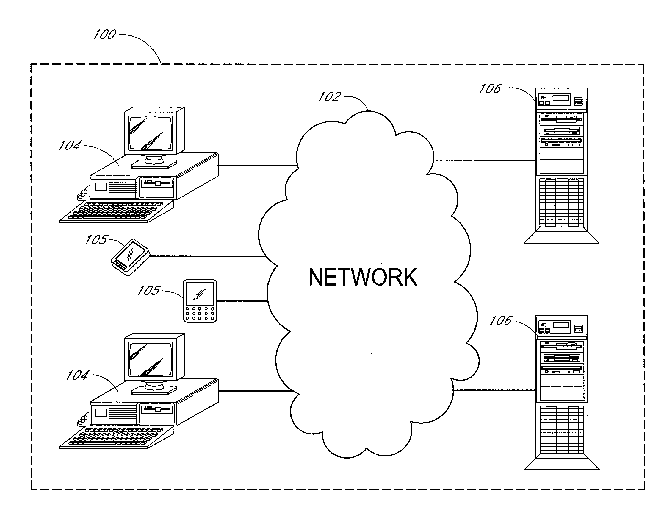
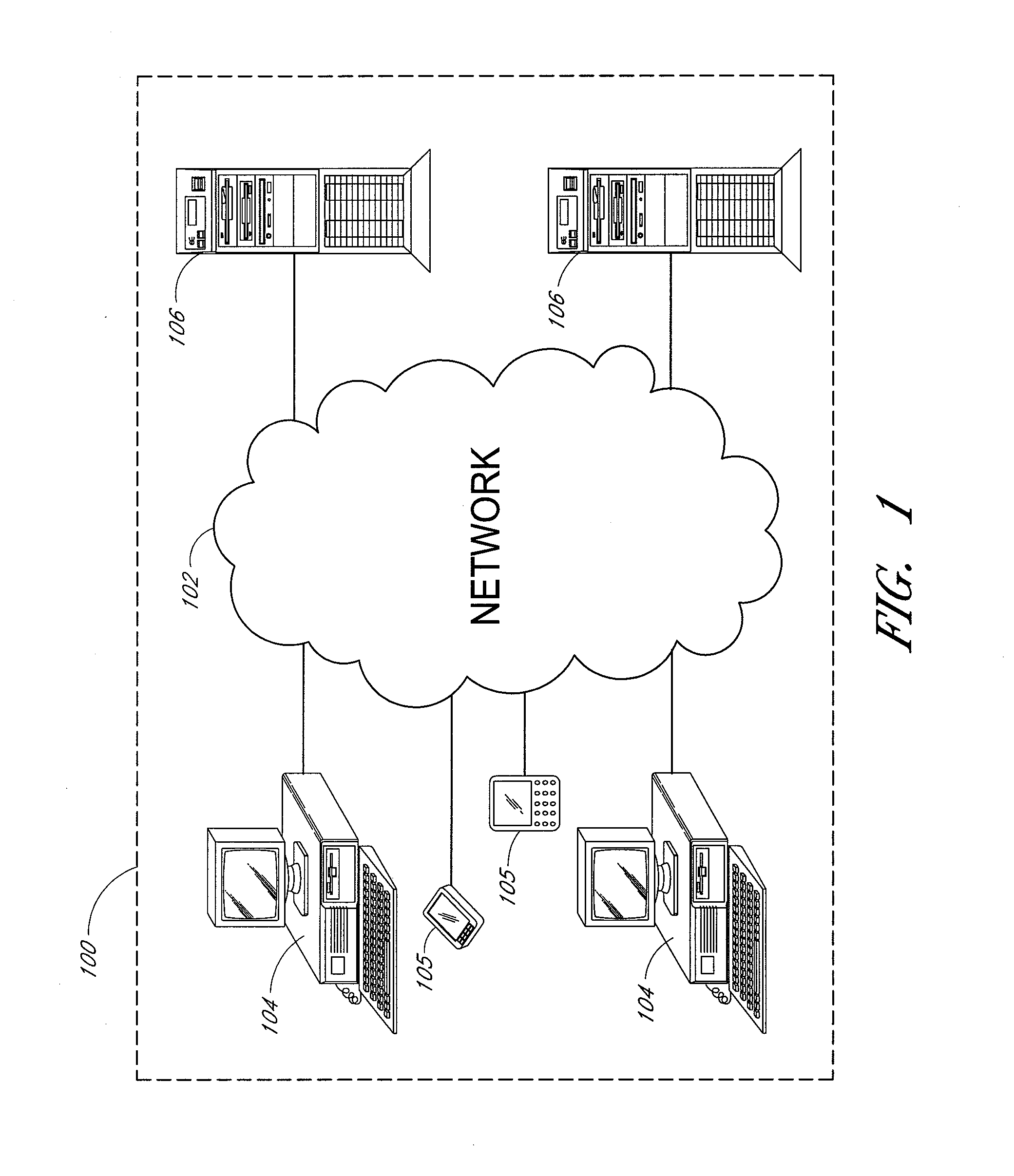
FIG. 1 shows an example of an overall environment 100 in which an embodiment of the invention may be used. The environment 100 includes an interactive communication network 102 with computers 104 connected thereto. Also connected to network 102 are mobile devices 105, and one or more server computers 106, which store information and make the information available to computers 104 and mobile devices 105. The network 102 allows communication between and among the computers 104, mobile devices 105 and servers 106.

Presently preferred network 102 comprises a collection of interconnected public and / or private networks that are linked to together by a set of standard protocols to form a distributed network. While network 102 is intended to refer to what is now commonly referred to as the Internet, it is also intended to encompass variations which may be made in the future, including changes additions to existing standard protocols. It also includes various networks used to connect mobile a...


PUM


Abstract

Embodiments of the invention comprise systems and methods for using the geographic location of networked consumer electronics devices as indications of occupancy of a structure for purposes of automatically adjusting the temperature setpoint on a thermostatic HVAC control. At least one thermostat is located inside a structure and is used to control an HVAC system in the structure. At least one mobile electronic device is used to indicate the state of occupancy of the structure. The state of occupancy is used to alter the setpoint on the thermostatic HVAC control to reduce unneeded conditioning of unoccupied spaces.

Description

BACKGROUND OF THE INVENTION1. Field of the InventionThis invention relates to the use of thermostatic HVAC and other energy management controls that are connected to a computer network. More specifically, the present invention pertains to the use of geographic movement of network-connected mobile devices to occupancy to inform an energy management system, to provide enhanced efficiency, and to verify demand response.2. Description of the Related ArtHeating and cooling systems for buildings (heating, ventilation and cooling, or HVAC systems) have been controlled for decades by thermostats. At the most basic level, a thermostat includes a means to allow a user to set a desired temperature, a means to sense actual temperature, and a means to signal the heating and / or cooling devices to turn on or off in order to try to change the actual temperature to equal the desired temperature. The most basic versions of thermostats use components such as a coiled bi-metallic spring to measure actu...

Claims


Application Information

Patent Timeline
Patent Type & Authority Applications(United States)
IPC IPC(8): G05D23/00H04W4/02H04W4/029
CPCF24F11/0034H04Q9/00G05D23/1905H04Q2209/40H04Q2209/84G05D23/1951F24F11/30F24F11/52F24F11/58F24F2120/10F24F2130/10F24F11/62F24F11/46F24F2130/00Y02D30/70H04W4/02H04W4/029
Inventor STEINBERG, JOHN DOUGLAS
Owner ECOFACTOR
Why Eureka
Try Eureka