Aircraft slat assembly

a technology for slats and aircraft, which is applied in the direction of wing adjustment, wing position indicators, and movable aircraft elements, etc., can solve the problems of excessive load, link interference with the lugs of the slat/track, and new airworthiness requirements that may now require the failure of actuators to be considered, so as to reduce the risk of joints being damaged by excessive skew

Active Publication Date: 2011-12-01
AIRBUS OPERATIONS LTD
View PDF49 Cites 28 Cited by
  • Summary
  • Abstract
  • Description
  • Claims
  • Application Information

AI Technical Summary

Benefits of technology

[0007]According to a first aspect of the invention, there is provided an aircraft slat assembly comprising a slat, two tracks and two joints, each joint connecting a respective track to the slat, and each track being moveable on a wing structure between a fully extended position and a stowed position, wherein each joint is arranged to allow relative rotation between the slat and the respective track such that the slat is able to adopt a skewed position in which one track is in the fully extended position and the other track is in the stowed position. By providing joints that allow the slat to adopt the most extreme skewed position, one of the tracks can continue to be driven (to or from the extended position) when the other track is inoperable. This reduces, and preferably removes, the risk of the joints being damaged by excessive skew. This also reduces, and preferably removes, the need for a warning and / or monitoring device associated with such a condition.

Problems solved by technology

The actuators used to move the slat are extremely robust and have met all the airworthiness requirements to date, but new airworthiness requirements may now require failure of an actuator to be considered.
In the above-mentioned slat assembly, the spherical bearings can accommodate a very small scale rotation of the slat, but under any substantive differential movement of the tracks (which would otherwise cause skew of the slat), the links would begin to interfere with the lugs on the slat / track and excessive loads may be generated.
These detection systems can be complex.
The detection systems also introduce a potential risk because in the event that the detection system malfunctions, the pilot may be able to continue to operate the slat assembly and thereby cause damage to the assembly.

Method used


Image

  • Aircraft slat assembly
  • Aircraft slat assembly
  • Aircraft slat assembly

Examples


Embodiment Construction

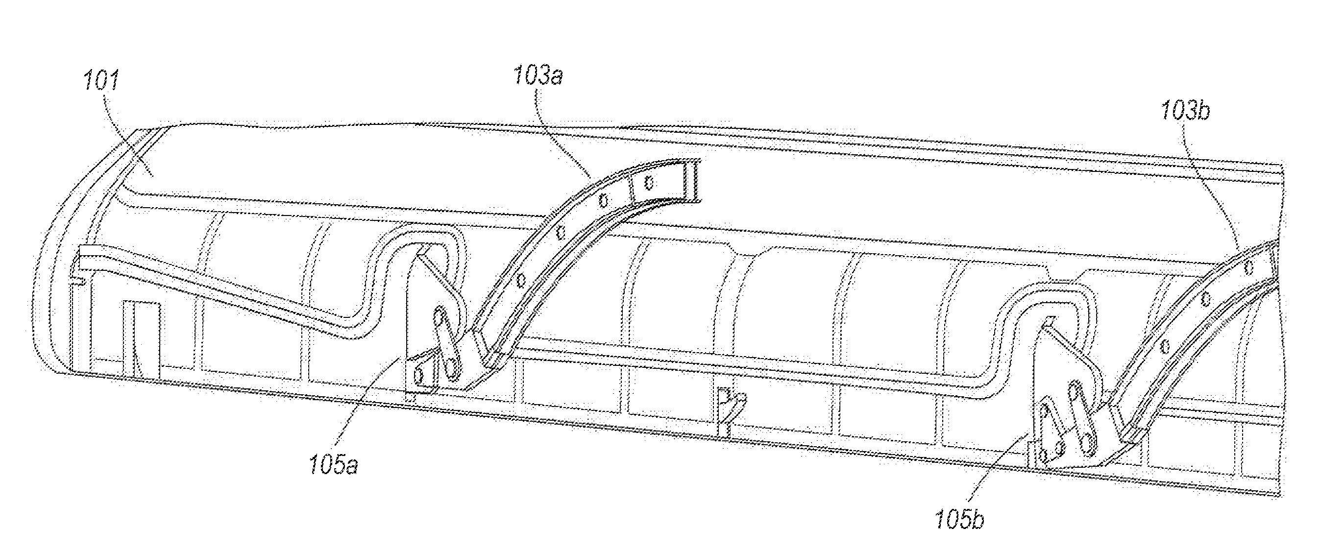
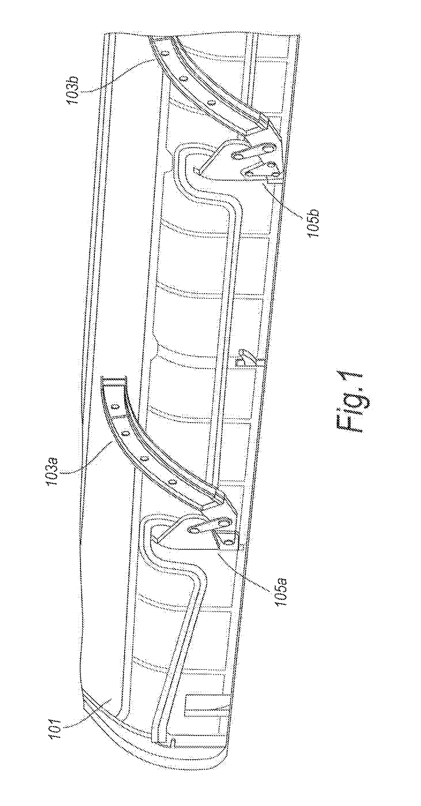
[0031]FIG. 1 is a rear perspective view of a known slat assembly. The assembly comprises a slat 101 connected to two arcuate tracks 103a, 103b mounted on a fixed wing structure (not shown). The tracks 103a, 103b are moveable relative to the fixed wing between an extended position in which the slat is deployed, and a stowed position, in which the slat is stowed on the fixed wing leading edge. The assembly comprises actuators (not shown) for moving the tracks 103a, 103b by way of a rack and pinion connection (not shown).

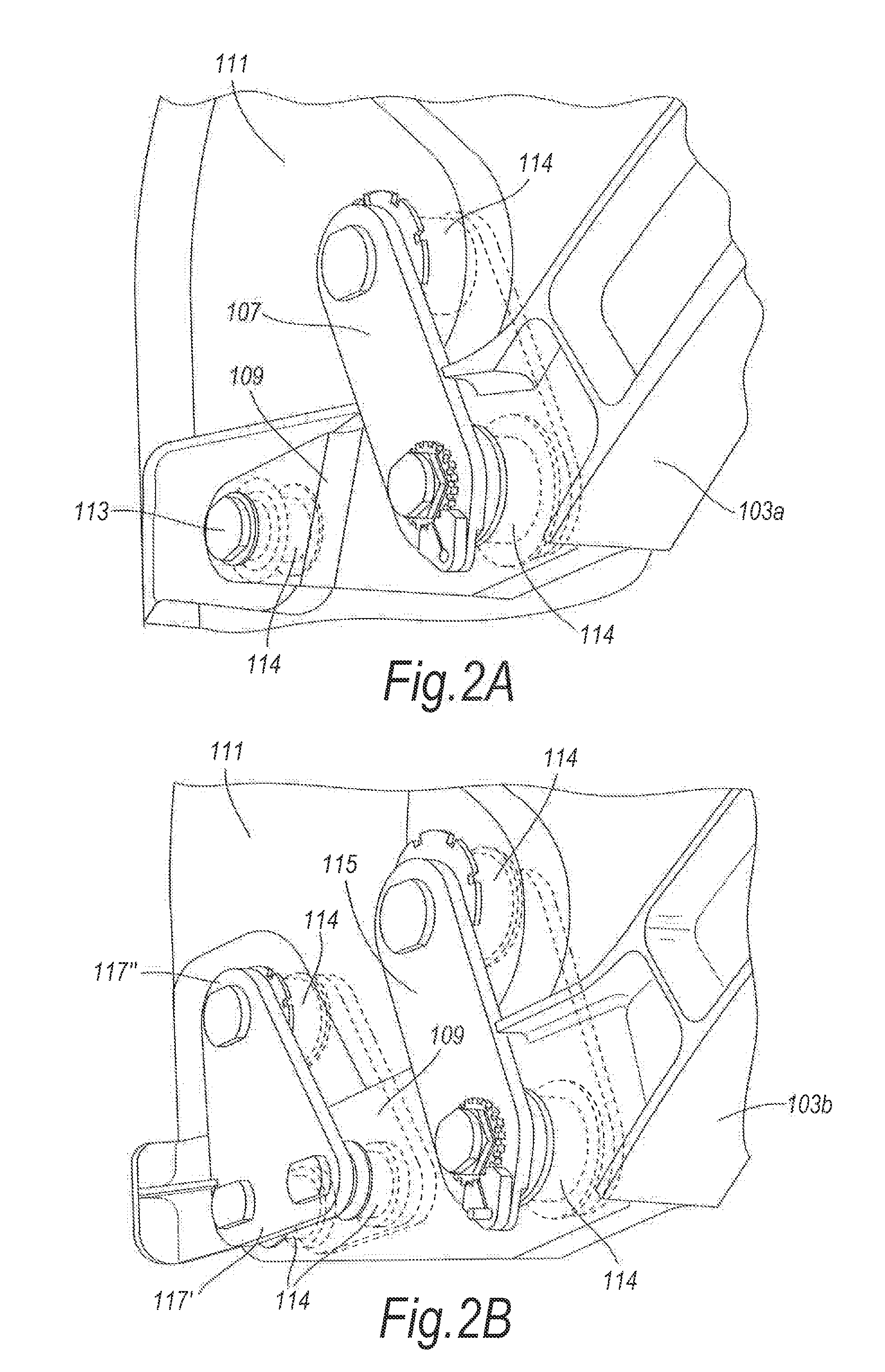
[0032]The tracks 103a, 103b are connected to the slat 101 by joints 105a, 105b (sometimes referred to as knuckle joints). In this known design, the first track 103a is connected to the slat 101 by a master joint 105a and the second track 103b is connected to the slat 101 by a sub-master joint 105b. The master joint 105a is shown in more detail in FIG. 2A and the sub-master joint is shown in more detail in FIG. 2B.

[0033]Referring first to FIG. 2A, the master joint 105a ...


PUM


Abstract

An aircraft slat assembly comprises a slat, two tracks and two joints, each joint connecting a respective track to the slat. Each track is moveable on a wing structure between a fully extended position and a stowed position. Each joint is arranged to allow relative rotation between the slat and the respective track such that the slat is able to adopt a skewed position in which one track is in the fully extended position and the other track is in the stowed position.

Description

TECHNICAL FIELD[0001]The present invention relates to an aircraft slat assembly, and more particularly to an aircraft slat assembly comprising a track-mounted slat.BACKGROUND OF THE INVENTION[0002]It is well known to provide a slat assembly comprising a slat connected to a plurality of tracks mounted on a fixed wing structure. The tracks are moveable relative to the fixed wing between an extended position in which the slat is deployed, and a stowed position, in which the slat is stowed on the fixed wing leading edge. The assembly typically comprises actuators for moving the tracks (for example by way of a rack and pinion connection). The shape of the tracks defines the position of the slat as it is deployed; the tracks may be a number of different shapes but are typically arcuate to define an arced forward and downward movement as the slat is deployed.[0003]The tracks are connected to the slat, by a joint (sometimes referred to as a knuckle joint). In a known design (shown in FIGS. ...

Claims


Application Information

Patent Timeline
Patent Type & Authority Applications(United States)
IPC IPC(8): B64C9/14B64C9/08B64C9/02B64C9/06B64C9/00B64C3/58
CPCB64D45/0005B64C9/22
Inventor PEIRCE, ROBERT JAMES
Owner AIRBUS OPERATIONS LTD
Why Eureka
Try Eureka