Winding shaft and method for inserting a winding shaft into a winding device

a technology of winding shaft and winding device, which is applied in the direction of shafts, shafts and bearings, thin material handling, etc., can solve the problems of unsuitable multi-use winding and handling difficulties, and achieve the effect of greater flexibility

Inactive Publication Date: 2016-06-16
REIFENHAUSER GMBH & CO
View PDF2 Cites 5 Cited by
  • Summary
  • Abstract
  • Description
  • Claims
  • Application Information

AI Technical Summary

Benefits of technology

The invention provides a winding shaft that is more flexible and adaptable for winding different materials. The shaft consists of a winding sleeve and shaft journals that can be easily detached and clamped onto the winding sleeve. This design allows for the winding of large parent rolls on a continuous winding sleeve without excessive weight or deflection. The winding sleeve is stable and made of metal or plastic, while the transition section between the shaft journal and the insertion section of the winding sleeue provides a stop for the winding sleeve and allows for different widths of the winding product. Overall, the invention provides a more efficient and flexible winding shaft for winding materials.

Problems solved by technology

Winding devices with laterally arranged mounts for continuous winding sleeves, however, usually cannot accommodate winding shafts, making them unsuitable for a multi-use winding.
In addition, when winding a narrow material web onto a winding device that is suitable for winding wide material webs, an unnecessarily wide winding sleeve must be kept on hand, which protrudes far beyond the finished winding and causes handling difficulties.

Method used


Image

  • Winding shaft and method for inserting a winding shaft into a winding device
  • Winding shaft and method for inserting a winding shaft into a winding device
  • Winding shaft and method for inserting a winding shaft into a winding device

Examples


Embodiment Construction

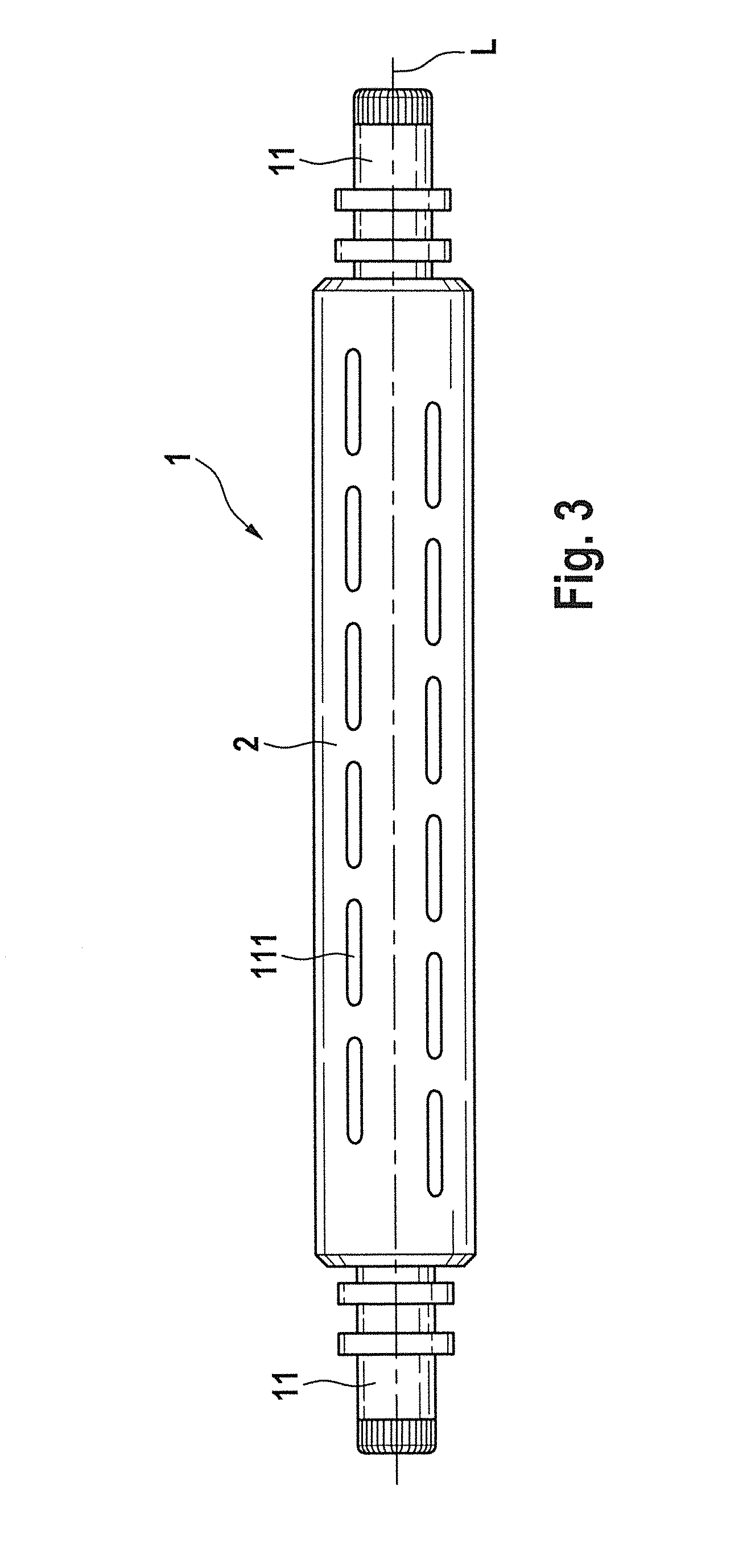
[0030]FIG. 3 shows a winding shaft according to the prior art, for insertion into a correspondingly embodied winding device.

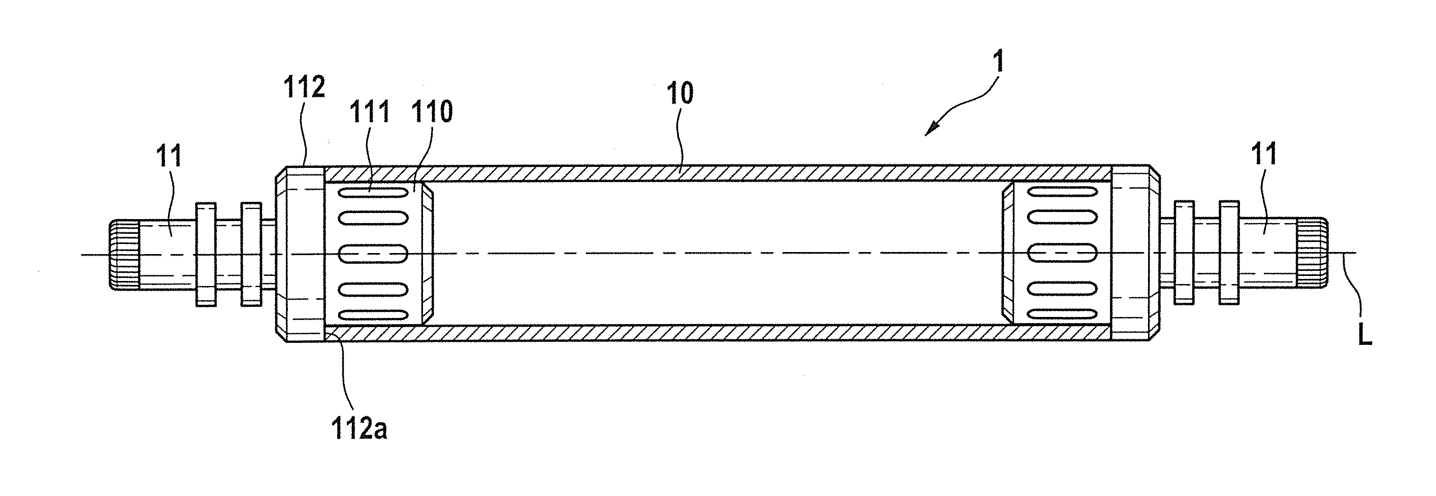
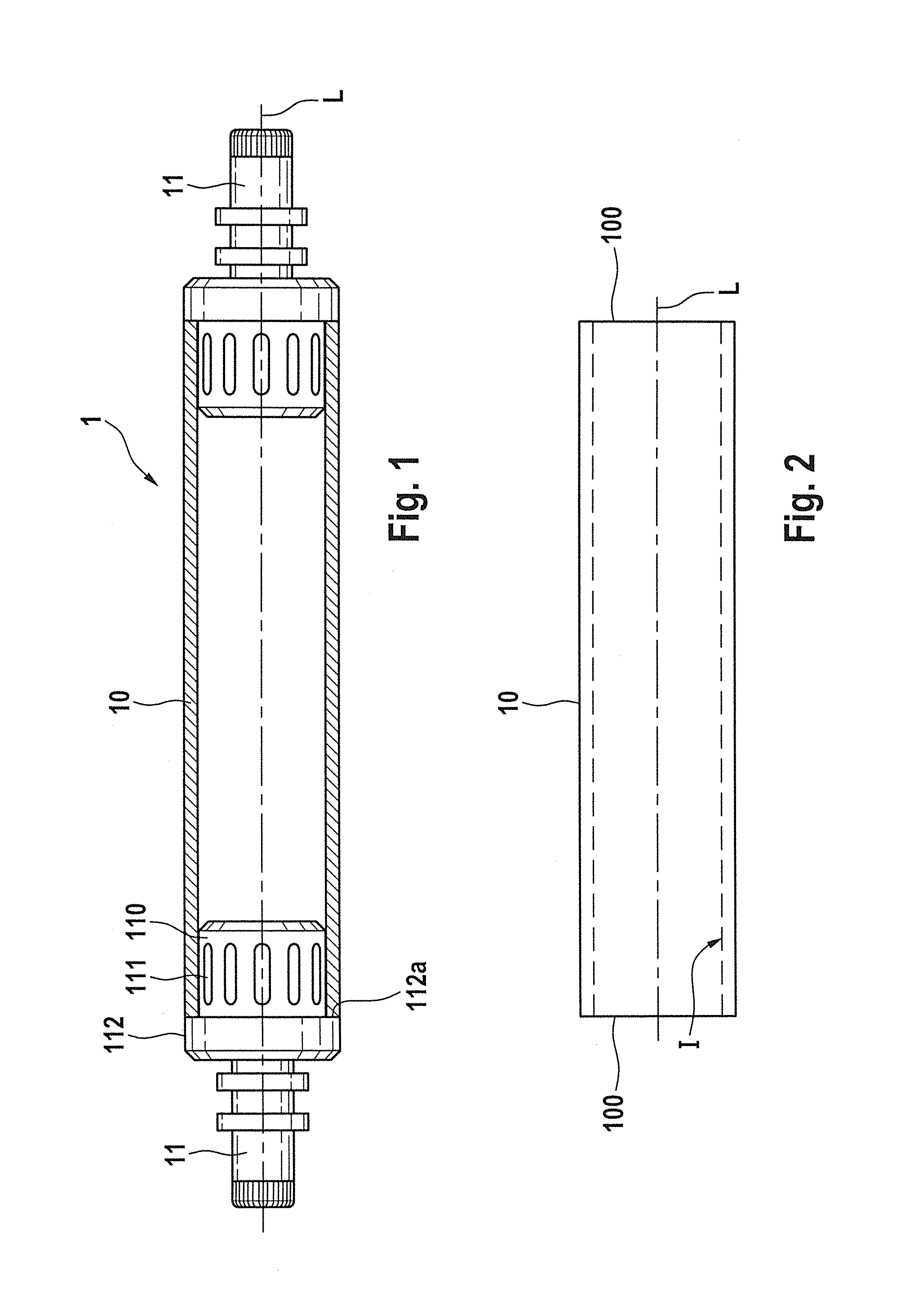
[0031]Such a winding shaft 1 includes a winding body 2 and at both ends of the winding body, shaft journals 11 are positioned on the longitudinal axis L and are configured for insertion into the winding device. The winding body 2 is embodied as intrinsically cylindrical and before being placed into use, is completed with a winding sleeve, not shown here, made of cardboard or the like, which is slid in a direction of the longitudinal axis L onto the winding body 2 so as to encompass the latter and is affixed to the winding shaft in a rotationally secured fashion by compressed air-operated clamping jaws 111 that can be radially extended out from the circumference of the winding body 2.

[0032]The cardboard sleeve that is affixed in this way can be embodied of one piece or of multiple pieces in order to thus enable a so-called multi-use winding.

[0033]After completio...


PUM


Abstract

A winding shaft with a winding body and shaft journals that are positioned or situated at the ends of the winding body and are configured for insertion into a winding device. The winding body is composed of a winding sleeve that is open at the ends and the shaft journals each has an insertion section with clamping, with which they can be inserted into the end of the winding sleeve and detachably clamped to the winding sleeve, and together with it, constitute the winding shaft. This invention also discloses a method for inserting a winding shaft into a winding device.

Description

BACKGROUND OF THE INVENTION[0001]1. Field of the Invention[0002]This invention relates to a winding shaft with a winding body and shaft journals that are positioned at the ends of the winding body and are configured for insertion into a winding device. This invention also relates to a method for inserting a winding shaft into a winding device, in which the winding shaft has a winding body and shaft journals that are positioned at the ends of the winding body, with which the winding shaft is inserted into corresponding recesses of the winding device.[0003]2. Discussion of Related Art[0004]Winding shafts for insertion into a winding device e.g. for winding web-like material such as webs of plastic film, fleece, and paper, are known and usually have a winding body equipped with winding journals at the ends of the winding body that are configured for insertion into the winding device and are held, for example, by corresponding winding arms of the device. In this connection, the winding ...

Claims


Application Information

Patent Timeline
IPC IPC(8): B65H18/04B65H75/24B65H19/22
CPCB65H18/04B65H75/243B65H19/22B65H2301/413B65H75/2437B65H75/2245B65H75/2254B65H19/30B65H75/08B65H75/185B65H2301/41346F16C3/023
Inventor MEYER, HELMUT
Owner REIFENHAUSER GMBH & CO
Why Eureka
Try Eureka