
Infusion management system and holder

a technology of which is applied in the field of infusion management system and holder, can solve the problems of extremely limited conventional iv pole system that is capable of simultaneously supporting medically-required items without adversely affecting patient mobility

Active Publication Date: 2011-12-01
FIREFLY MEDICAL
View PDF6 Cites 39 Cited by
  • Summary
  • Abstract
  • Description
  • Claims
  • Application Information

AI Technical Summary

Benefits of technology

[0012]In an aspect, the holder apparatus further comprises an alignment holder. The alignment holder can help facilitate positioning of the IMS with the holder, and particularly the trunk and the head. The alignment holder may comprise a rotatable release hook connected to the head and a rotatable release handle rotatably connected to the rotatable release hook. “Rotatably connected” refers to the rotation of one element resulting in rotation of a second element. In this aspect, rotation of the release handle rotates the rotatable release hook to align and secure an infusion management system to the head of the holder, or to facilitate removal of an infusion management system from the head of the holder, such as by interaction with an actuation slot in the trunk. In an aspect, engagement of the release hook with the actuation slot activates or pulls a release mechanism in the infusion management system that permits the base arms to rotate to and from a stowed state. Accordingly, for safety during use of the IMS the base arms, in an aspect, can only rotate relative to the trunk when the actuation slot is engaged, such as by engagement of the wall mount release hook with the actuation slot to pull a release mechanism in the actuation slot of the IMS.
[0014]In an aspect, the apparatus further comprises a guide face having a surface that substantially conforms to a trunk surface of the infusion management system and a release hook slot positioned in the guide face, wherein the rotatable release hook at least partially extends through the release hook slot. In an embodiment, the guide face surface is shaped or contoured to conform to the trunk surface that is to-be-positioned adjacent to the guide face surface. For example, the guide face surface may be at least partially concave to accommodate a convex shaped trunk surface. Such a configuration facilitates intimate contact between the trunk surface and the head.
[0021]In another embodiment, the IMS further comprises an actuation slot in the trunk; wherein the release hook in the head is operably connected to the actuation slot. In this configuration, the release hook can assist in IMS alignment with the holder and also in storing and releasing the IMS from the apparatus and the holder in the head.

Problems solved by technology

In the medical field, conventional IV pole systems that are capable of simultaneously supporting medically-required items without adversely affecting patient mobility are extremely limited, as discussed in U.S. Pat. Pub.

Method used


Image

  • Infusion management system and holder
  • Infusion management system and holder
  • Infusion management system and holder

Examples


example 1

Wall-Mountable Holder for Storing an IMS

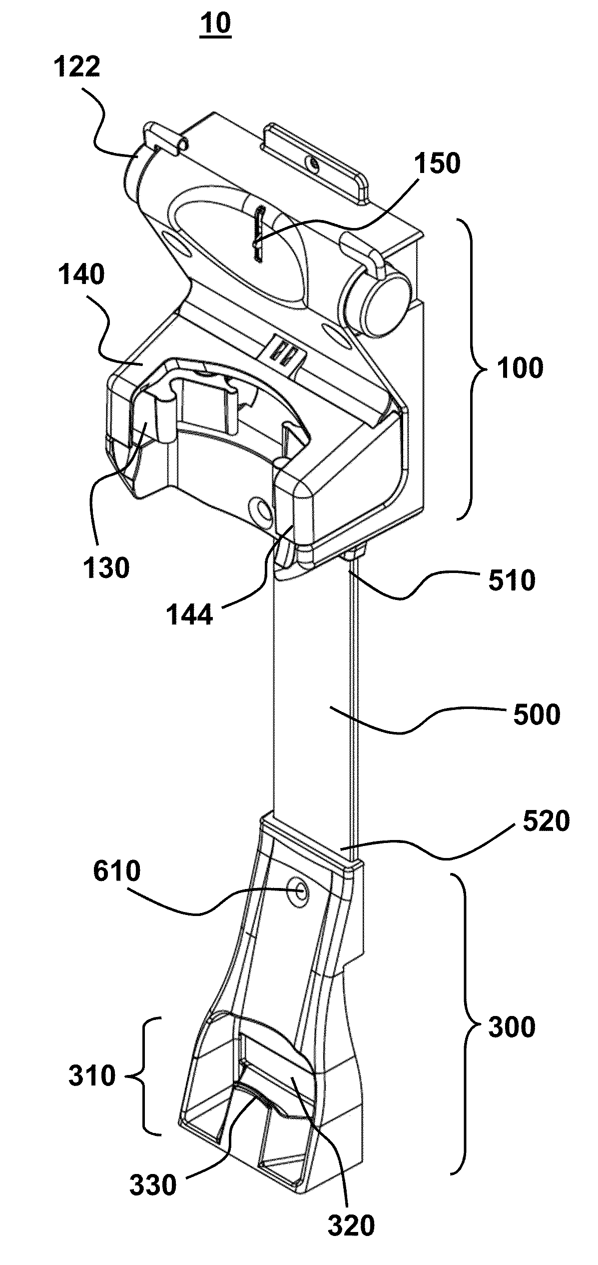
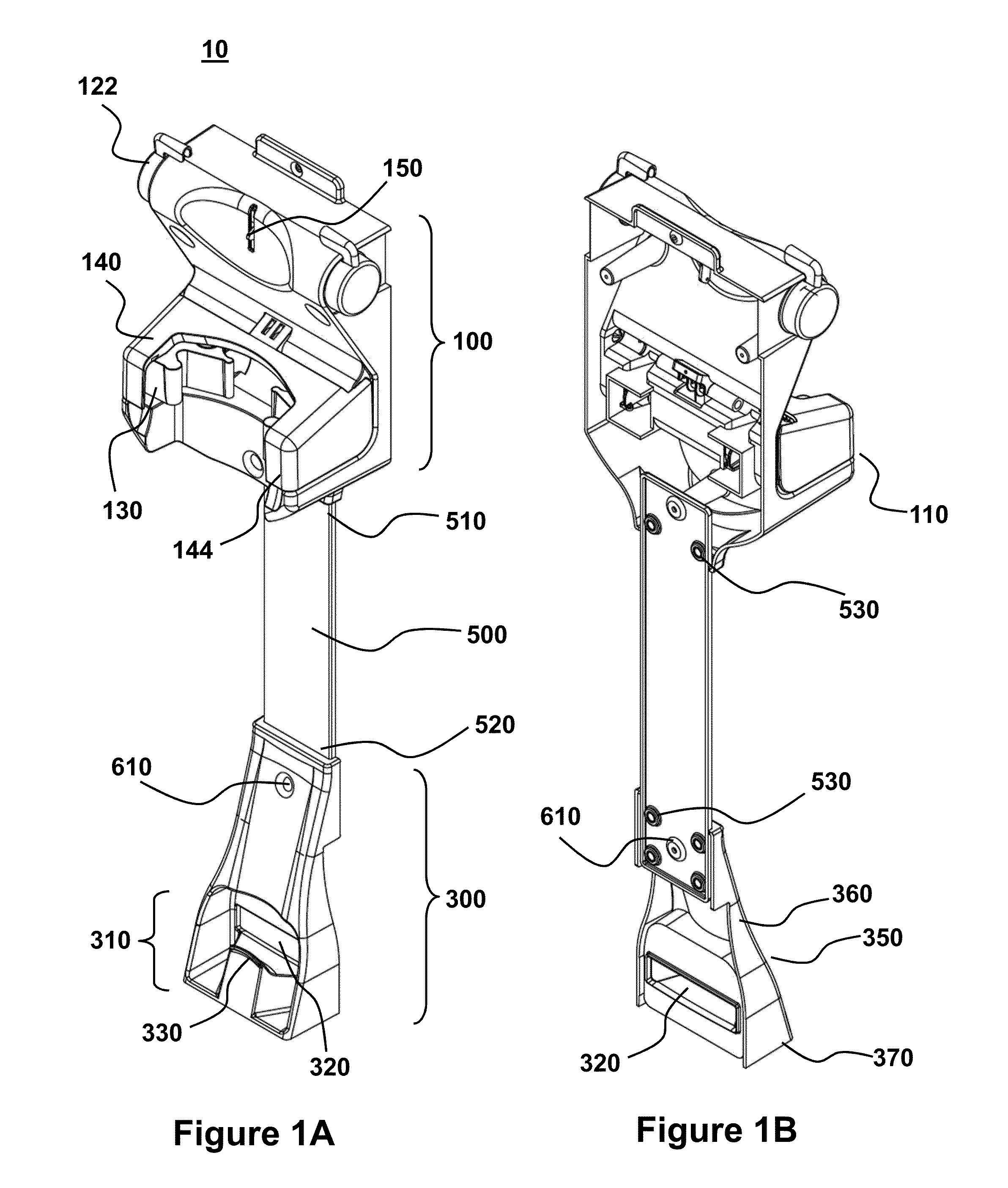
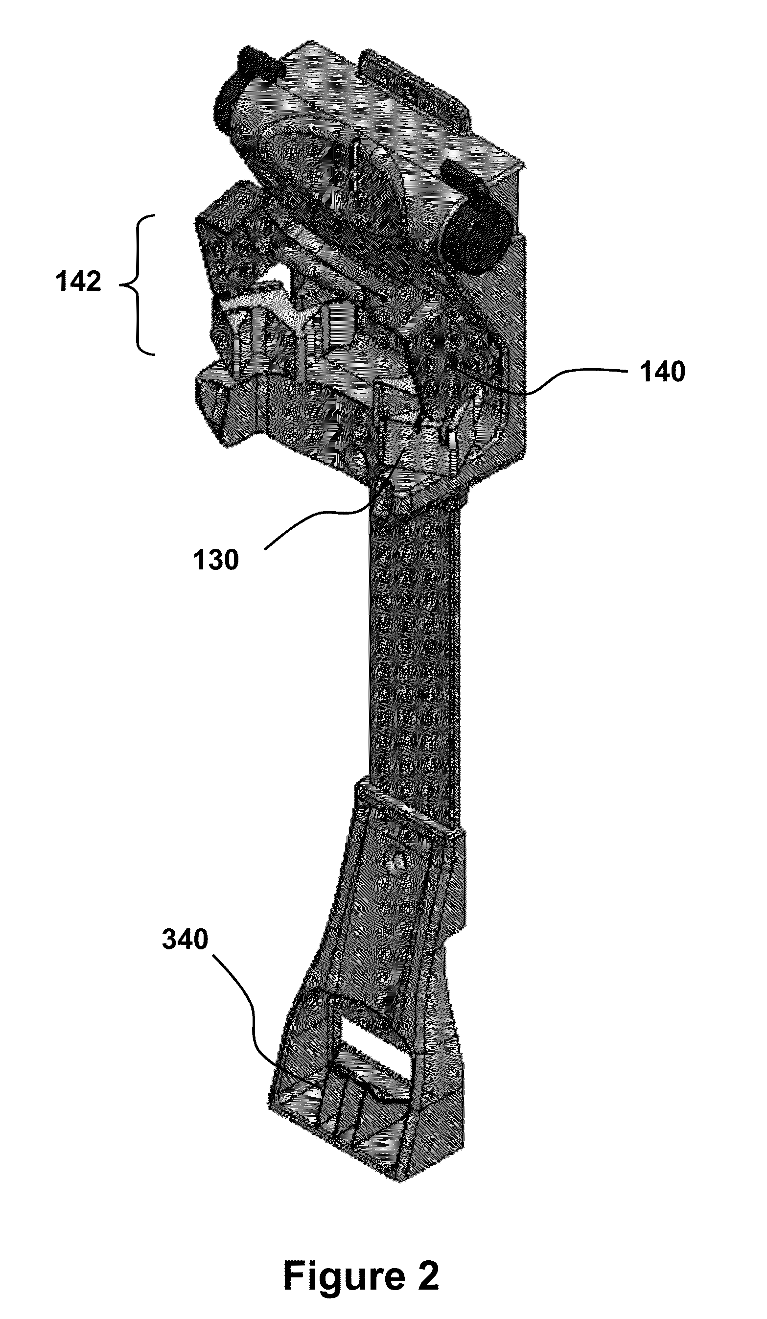
[0048]FIGS. 1-2 are schematics of a holder designed to be connected to a surface, such as a wall, and to which an IMS may be compactly and conveniently stored. In this embodiment, the apparatus holder 10 comprises a head 100, a foot 300, and a neck 500 that is connected to the head at a neck first end 510 and to the foot at a neck second end 520, such as at connection points or fasteners 530 at ends 510 and 520. Neck 500 is an optional component that can be used to provide additional structural support to the overall holder 10 and to assist in positioning the head 100 and foot 300 and, in particular, facilitate precise separation between those portions to ensure good fit to an IMS that is to be mounted to holder 10.

[0049]In operation, the head 100 functions to reliably secure a trunk portion of the IMS, such as by a holder 110. In the embodiment illustrated in FIG. 1, the holder 110 further comprises a pair of flappers 130 that are vertically ...

example 2

IMS Configured for Use with the Holder of Example 1

[0052]The holder may be configured and design to mate to any number of different pieces of equipment that compactly fold and present an available longitudinal axis for the holder. In an embodiment, the holder is for use with an IMS, including the IMS disclosed in U.S. Pat. Pub. No. 2008 / 0156946 (which is hereby specifically incorporated by reference for the IMS disclosed therein). In an embodiment, the holder is configured to hold any of the IMS provided herein, including the embodiment illustrated in FIGS. 3-5.

[0053]In an embodiment, the IMS is configured for stability and maneuverability, even under a heavy load. Furthermore, the IMS is capable of being compactly stored when not in use when connected to the holder apparatus disclosed herein. Referring to FIG. 3, IMS stability is achieved by providing a relatively large base footprint formed by base arms 730 and 740 and a trunk 710 angled to ensure the center of mass of the system ...

example 3

Holder Head

[0059]FIGS. 7-10 illustrate an embodiment of the holder head 100. FIG. 7 is the housing portion of the head that accommodates various elements of the head. The left panel is front view showing the release slot 152 for accommodating the rotatable release hook and a release handle surface 162 for accommodating a rotatable release handle 160 (shown in FIG. 8). The housing is configured to provide various pivots for operably connected the locking hood and the flappers. Various bosses are provided to facilitate mounting and alignment of the head.

[0060]FIG. 8 illustrates the housing of FIG. 7 in combination with various elements for securing the IMS trunk. The front view (right panel) shows the release handles, rotatable release hook, locking hood and flappers connected to the housing. Rotation of release handles by a user provides a corresponding rotation of the release hook. The pivot directions of the locking hood and flappers are perpendicular to each other and is one examp...


PUM


Abstract

Provided are holders for compactly storing infusion management systems to surfaces. In an embodiment the holder apparatus has a head portion for receiving and infusion management system trunk portion and a foot for receiving an apex portion of the infusion management system. The holder apparatus may be mounted to a wall so that the infusion management system is compactly stored and then mounted against the wall, thereby dramatically decreasing the storage footprint of the systems when not in use, without sacrificing the ability to conveniently and rapidly deploy the system when needed. Also provided are infusion management systems configured for use with the holder apparatus and related methods of storing the system.

Description

CROSS-REFERENCE TO RELATED APPLICATIONS[0001]This application claims benefit of U.S. Provisional Patent App. No. 61 / 301,843 filed Feb. 5, 2010, which is hereby incorporated by reference to the extent not inconsistent with the disclosure herein.BACKGROUND OF THE INVENTION[0002]Despite the ongoing and growing demand for patient mobility, load capacity, multi-functionality, safety and stability, the basic IV pole design has not significantly changed since the 1920's. Thus, it is not surprising that the basic IV pole design is obsolete and represents, at best, a nuisance and in many situations a hazard for both patients and patient caregivers, including hospital personal. Not uncommonly, the basic IV pole is prone to tipping, especially on carpets and when encountering bumps or any surface transitions (e.g., elevator, carpet / hard surface transition, doorways, etc.).[0003]As the complexity of medical care has increased, so has the number, amount and weight of medical materials needed to ...

Claims


Application Information

Patent Timeline
IPC IPC(8): F16M13/02F16M13/00B23P17/04
CPCA61M5/1415Y10T29/49826A61M5/1417
Inventor HENAULT, MARKKOLOZS, JAMESCOLE, SEANMCKONLY, CHADCOOPER, CHARLES
Owner FIREFLY MEDICAL
Features
  • Generate Ideas
  • Intellectual Property
  • Life Sciences
  • Materials
  • Tech Scout
  • Unparalleled Data Quality
  • Higher Quality Content
  • 60% Fewer Hallucinations
Learn More