
Pillow block seal

a pillow block and seal technology, applied in the direction of roller bearings, rigid supports of bearings, mechanical equipment, etc., can solve the problems of premature wear and failure of bearings, lubrication to become contaminated, and provide an adequate operating li

Inactive Publication Date: 2011-12-01
ALCO INDS
View PDF7 Cites 6 Cited by
  • Summary
  • Abstract
  • Description
  • Claims
  • Application Information

AI Technical Summary

Benefits of technology

The present invention provides a seal for a pillow block carrying a rotating shaft, which includes an annular body with an inner surface and an outer surface, a retaining channel defined by the inner surface, and at least a first ring and a second ring disposed within the retaining channel. The seal also includes a rotating collar having an opposed inner and outer surface, a fixed annular body disposed in an interface aperture of the pillow block, and at least a first ring and a second ring disposed within the retaining channel. The seal and the pillow block carrying the rotating shaft can be used in various applications such as industrial equipment and machinery.

Problems solved by technology

These seals come in direct contact with the rotating shaft, resulting in friction that causes them to wear.
The worn seals gradually allow the intrusion of particles and other debris into the pillow block, causing the lubrication to become contaminated.
This contamination ultimately leads to the premature wear and failure of the bearing, thus necessitating its replacement, which is undesirable.
Thus, seals that are currently in use do not provide an adequate operating life, which leads to the premature failure of the pillow block bearing.

Method used


Image

  • Pillow block seal
  • Pillow block seal
  • Pillow block seal

Examples


Embodiment Construction

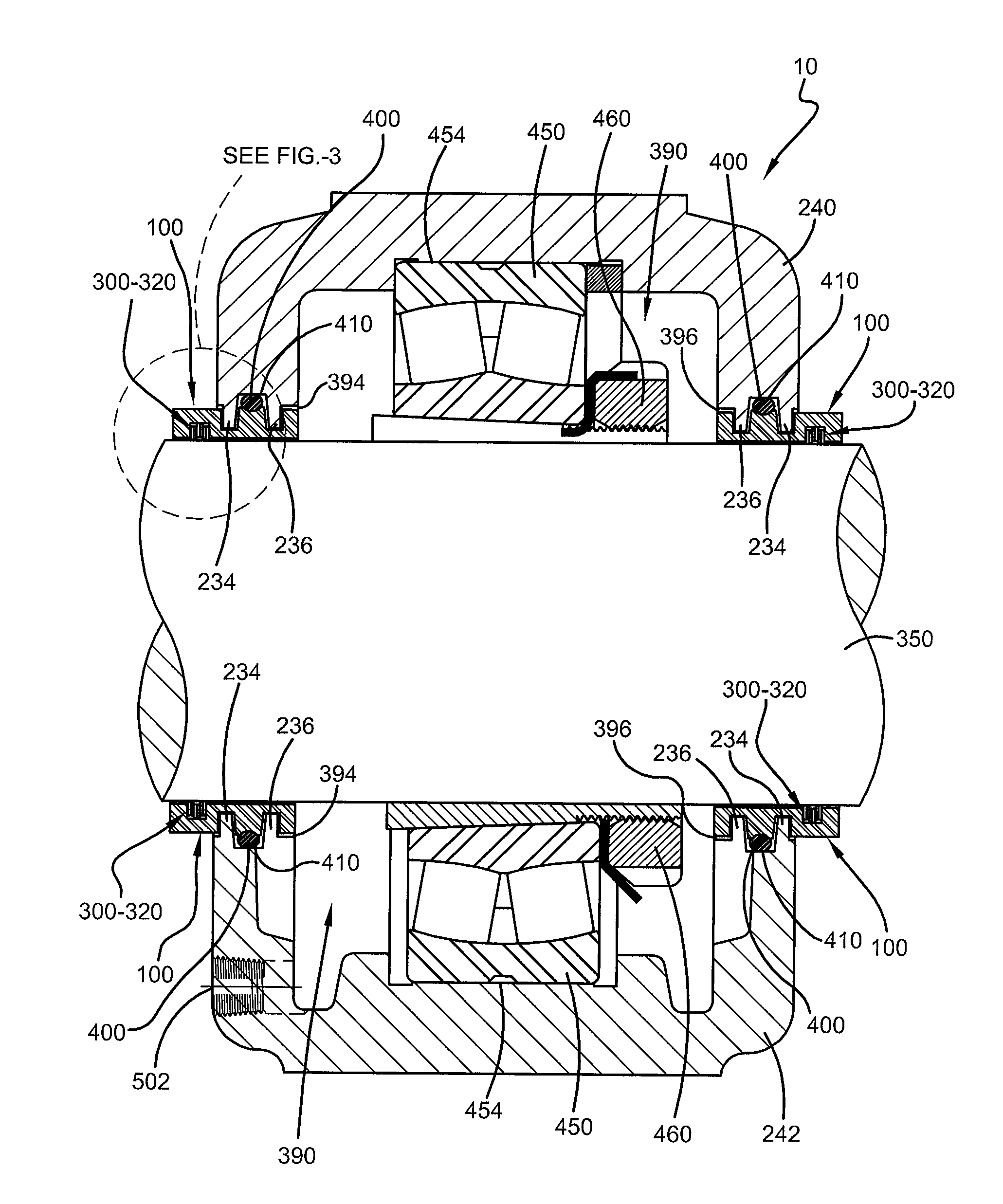
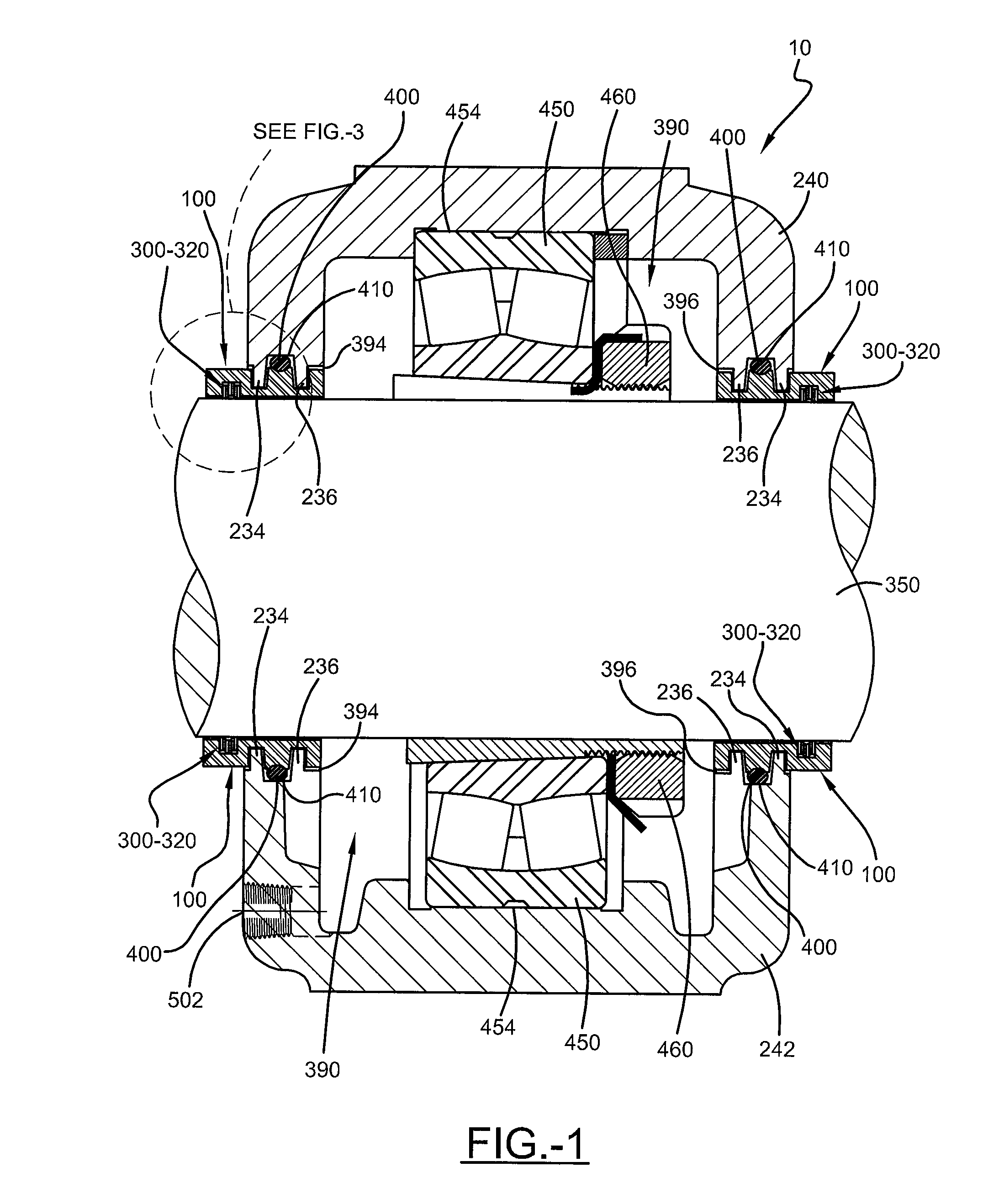
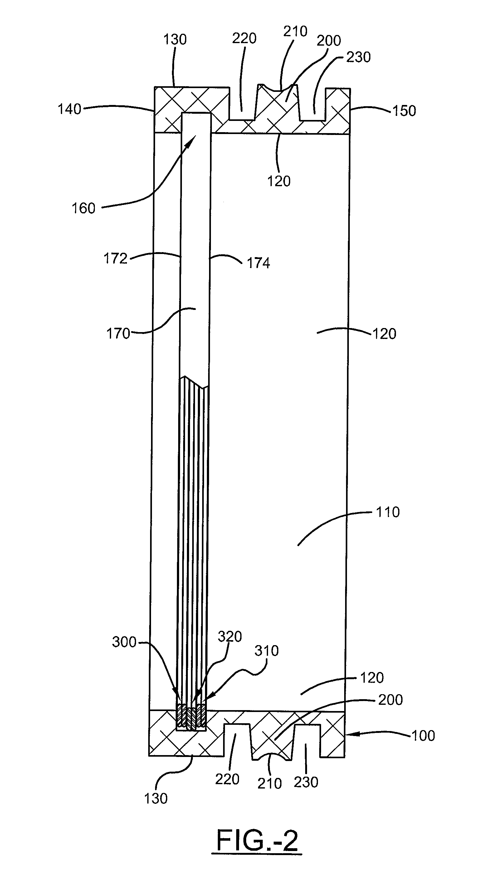
[0019]A seal for a pillow block 10 is generally referred to by the numeral 100, as shown in FIGS. 1-5A of the drawings. Shown clearly in FIG. 3, the seal 100 comprises an annular body 110 having opposed inner and outer surfaces 120 and 130 that are bounded by opposed front and rear edges 140 and 150. Circumferentially disposed about, or otherwise defined by, the inner surface 120 proximate to the front edge 140 of the seal body 110 is a retaining channel 160 that is defined by an annular channel wall 170 that is bounded by opposed lateral retaining walls 172,174 that extend therefrom at a substantially right angle. Extending from the outer surface 130 of the body 110 is an annular ring support 200, which includes a curved retention groove 210 thereon. The ring support 200 is positioned between a pair of mounting channels 220 and 230 that are spaced and dimensioned to receive corresponding engagement protrusions 234 and 236 provided by top and bottom case sections 240, 242 that compr...


PUM


Abstract

A seal for a pillow block that supports a rotating shaft includes an annular body having an inner surface opposite an outer surface. Disposed in the inner surface is a retaining channel that retains two double-wound laminar gripping rings that are separated by a double-wound laminar engagement ring. The gripping rings are dimensioned to frictionally engage and are carried by the shaft as it rotates. The engagement ring remains fixed within the retaining channel relative to the rotating gripping rings, resultantly forming a labyrinth seal to prevent the intrusion of particles and debris from entering the pillow block to prevent the contamination of lubricants contained therein.

Description

TECHNICAL FIELD[0001]Generally, the present invention relates to a seal for protecting bearings. More particularly, the present invention relates to a seal for a pillow block that utilizes laminar rings to form a labyrinth seal about a rotating shaft carried thereby.BACKGROUND ART[0002]Pillow blocks are typically used to house and retain a self-aligning bearing that carries a rotating shaft. In addition, the pillow block also serves to maintain lubricants, such as grease and oil, so that they are in continuous contact with the moving components of the bearing. In order to prevent particles, such as dirt and other debris, from damaging the bearing, seals are provided at each interface where the shaft extends through the pillow block. These seals come in direct contact with the rotating shaft, resulting in friction that causes them to wear. The worn seals gradually allow the intrusion of particles and other debris into the pillow block, causing the lubrication to become contaminated. ...

Claims


Application Information

Patent Timeline
Patent Type & Authority Applications(United States)
IPC IPC(8): F16J15/447F16C33/72
CPCF16C35/047F16C33/80F16C19/38F16C23/086F16C33/586F16C33/76F16C33/768F16C35/073F16C2226/16
Inventor BARTLEY, KEITH ALLEN
Owner ALCO INDS
Learn More