
Screw with double notches

a screw and notch technology, applied in the field of screw with double notch, can solve the problems of increasing drilling resistance, affecting the construction of the cutting notch b>14/b>, and affecting the performance of the screw, so as to prevent the damage of the fastened object, increase the drilling torque, and enhance the drilling speed

Active Publication Date: 2011-12-01
ESSENCE METHOD REFINE
View PDF18 Cites 7 Cited by
  • Summary
  • Abstract
  • Description
  • Claims
  • Application Information

AI Technical Summary

Benefits of technology

[0008]It is therefore the purpose of this invention to provide a screw with double notches for decreasing the drilling torque and enhancing the drilling speed, thereby preventing a fastened object from damage, and thence avoiding the screw from breaking in time of operation.

Problems solved by technology

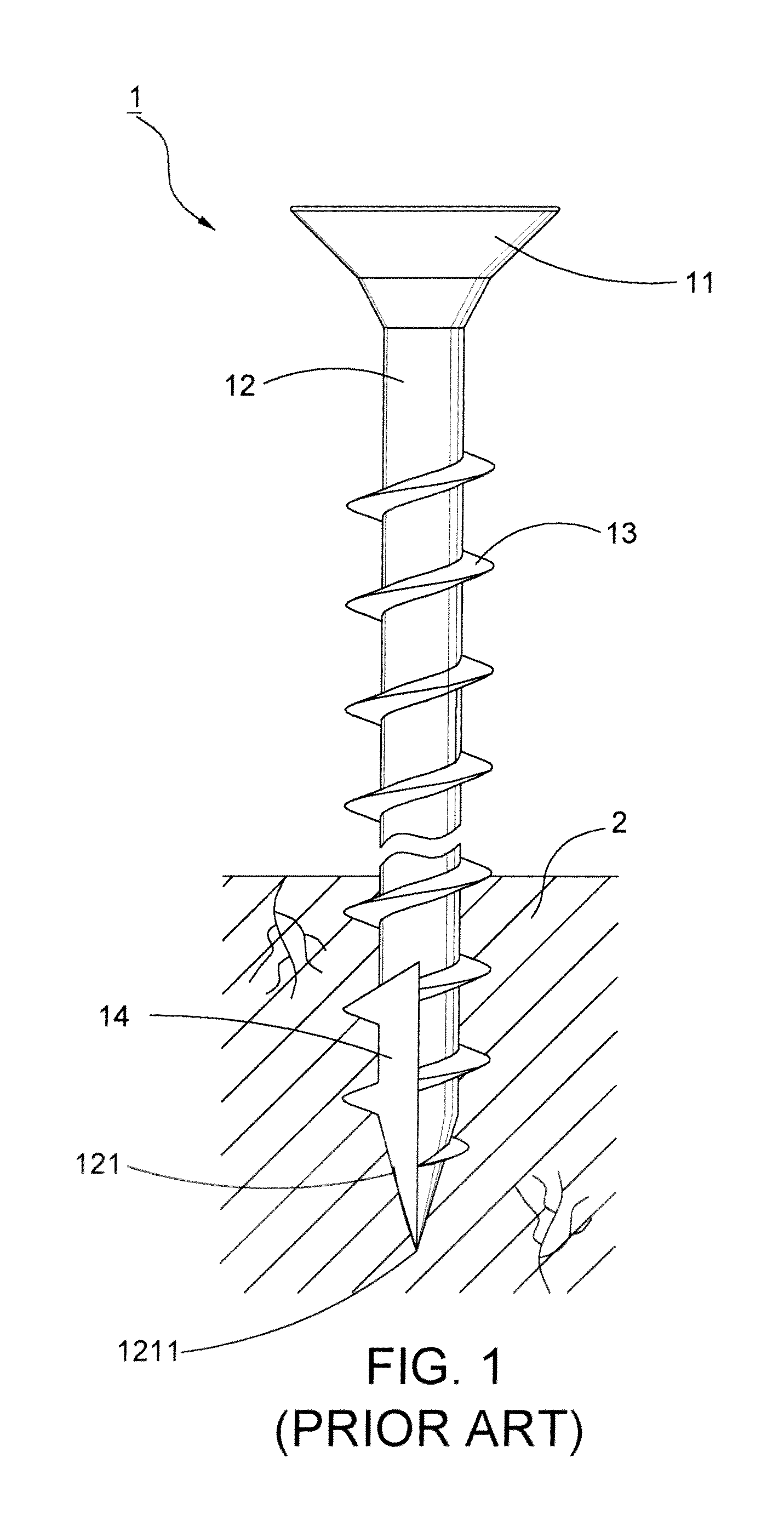
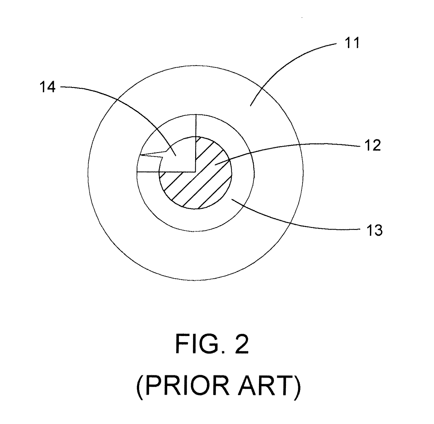
1. The single cutting notch 14 is in fact unable to thoroughly sever the wood fiber of the object 2 tangling on the shank portion 12. Thus, the unsevered wood fiber adversely results in the increased drilling resistance. Moreover, the sole cutting notch 14 on the shank portion 12 cannot provide an adequate room for accommodating and timely extruding debris. Thus, the debris that is untimely extruded will block up the cutting notch 14, and the situation even becomes worse since the rest of the debris subsequently enters the constricted cutting notch 14. As a result, the crowded cutting notch 14 thence brings about a split object 2.
2. As aforementioned, the debris blocking up the constricted cutting notch 14 unbeneficially increases the drilling resistance and influences the drilling speed. Herein, if the object 2 is made of a material having the property of high density, more drilling torque imparted on the screw 1 is thence needed as a huge drilling resistance occurs on the blocked cutting notch 14. As a result, the construction on the cutting notch 14 might be abraded, and the shank portion 12 might be broken.

Method used


Image

  • Screw with double notches
  • Screw with double notches
  • Screw with double notches

Examples


Embodiment Construction

[0029]Wherever possible, the same reference numbers are used in the drawings and the description to refer to the same or like parts.

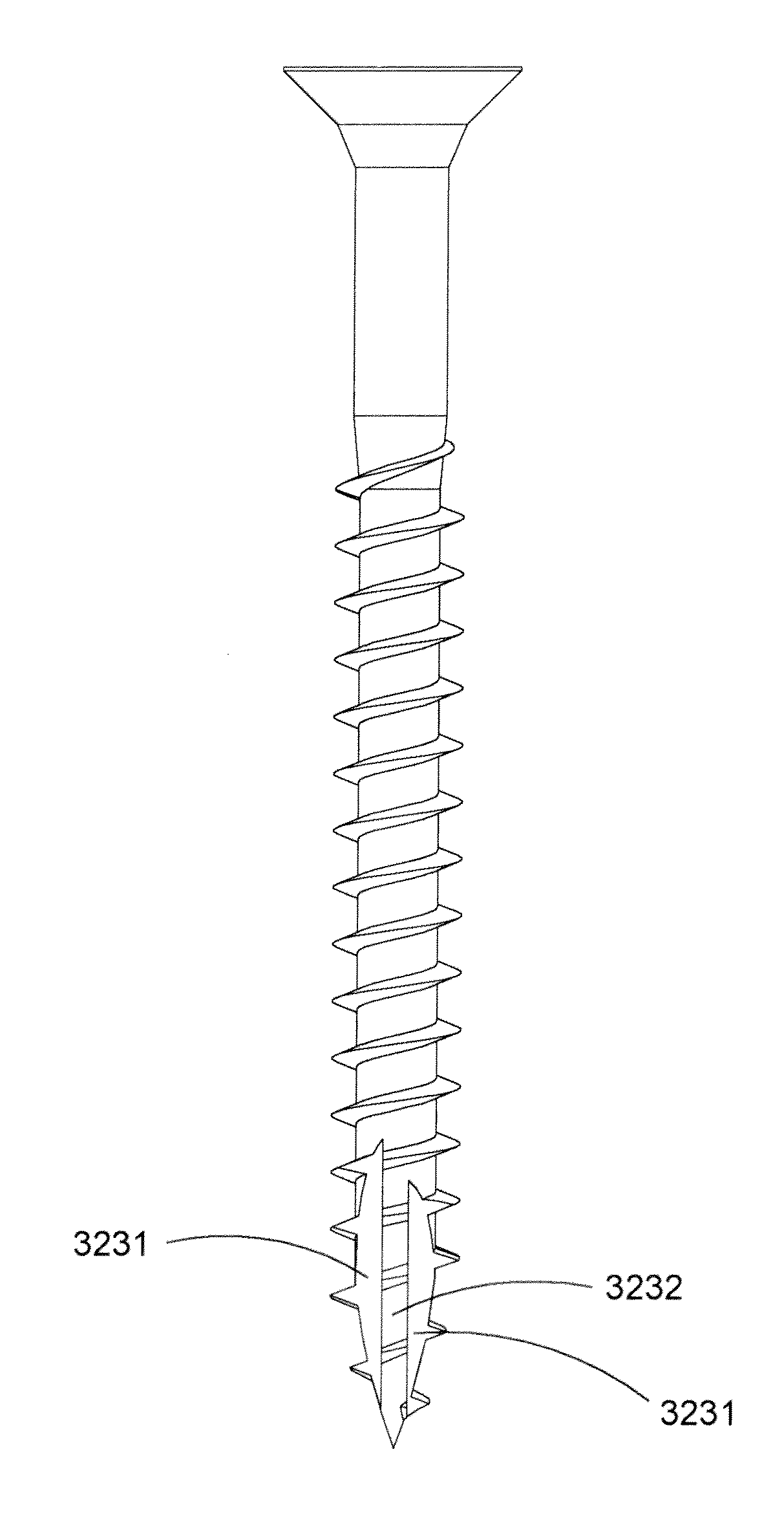
[0030]Referring to FIGS. 3 and 4, a first preferred embodiment of the present invention is shown. A screw 3 with double notches comprises a head portion 31, a shank portion 32 extended outward from the head portion 31, and a threaded section 33 spirally surrounded on the shank portion 32. Wherein, the shank portion 32 comprises a drilling portion 321 formed at one end thereof, opposite to the head portion 31, a drilling tip 3211 disposed at a distal end of the drilling portion 321, and an axis α defined along a center of the shank portion 32.

[0031]Continuingly, the shank portion 32 is cross-sectionally divided into a raw section 322 and a notched section 323 disposed relatively to the raw section 322. Wherein, the raw section 322 is provided with an cambered surface formed integral with the shank portion 32 in cross-section, and the notched section 323 ...


PUM


Abstract

A screw with double notches includes a head portion, a shank portion extended outward from the head portion, a threaded section spirally surrounded on the shank portion. Wherein, a raw section on the shank portion is provided with a cambered surface formed integral with the shank portion in cross-section, and a notched section relative to the raw section has two cutting notches separately depressed into the shank portion and disposed near an end of the shank portion, thereby forming a protrudent part between the two cutting notches. By means of the cooperation of the cutting notches and the raw section, the cutting capability and the removal of debris are increased so that a fastened object is prevented from split. Thereby, the drilling speed is promoted, and the effort to rotate the screw is lessened. While the supporting strength of the screw is improved, the screw does not break easily while screwing.

Description

BACKGROUND OF THE INVENTION[0001]1. Field of the Invention[0002]The present invention relates to a screw, particularly to a screw with double notches.[0003]2. Description of the Related Art[0004]Referring to FIGS. 1 and 2, a conventional screw 1 comprises a head portion 11, a shank portion 12 extended outward from the head portion 11, a threaded section 13 spirally surrounded on the shank portion 12, and a cutting notch 14 defined on the shank portion 12. Wherein, a drilling portion 121 is formed on one end of the shank portion 12, opposite to the head portion 11. A drilling tip 1211 is further defined on a distal end of the drilling portion 121. The cutting notch 14 is defined on the shank portion 12 and extended toward the drilling portion 121. By imparting a drilling torque upon the head portion 11, the threaded section 13 is able to assist the screw 1 in drilling into an object 2. Herein, the cutting notch 14 preferably scrapes away and severs the wood fiber of the object 2 into...

Claims


Application Information

Patent Timeline
IPC IPC(8): F16B25/10
CPCF16B25/103
Inventor CHANG, CHING-HSIANG
Owner ESSENCE METHOD REFINE
Learn More