Terminal table fastener

a technology of terminal table and fastener, which is applied in the direction of clamped/spring connection, electrical apparatus, connections, etc., can solve the problems of large force, insufficient hardness of the fastener, and inability to bear the expected torsion, etc., and achieves high rigidity, low cost, and high torque

Inactive Publication Date: 2011-12-01
ANYTEK TECH CORP LTD
View PDF10 Cites 17 Cited by
  • Summary
  • Abstract
  • Description
  • Claims
  • Application Information

AI Technical Summary

Benefits of technology

[0006]To obviate the deficiencies above, an object of the present invention is to provide a terminal table fastener which has low cost, high rigidity and large torque, and which has optimal retention and reliable electrical conduction.

Problems solved by technology

Other fasteners, such as fasteners made by forging zinc alloy or machining brass, are not hard enough, and can not bear expected torsion.
Moreover, in process of forging, force is so large that takes risk of splitting or abrading teeth of the screws.
So it needs much too cost and is uneconomical.

Method used


Image

  • Terminal table fastener
  • Terminal table fastener
  • Terminal table fastener

Examples


Embodiment Construction

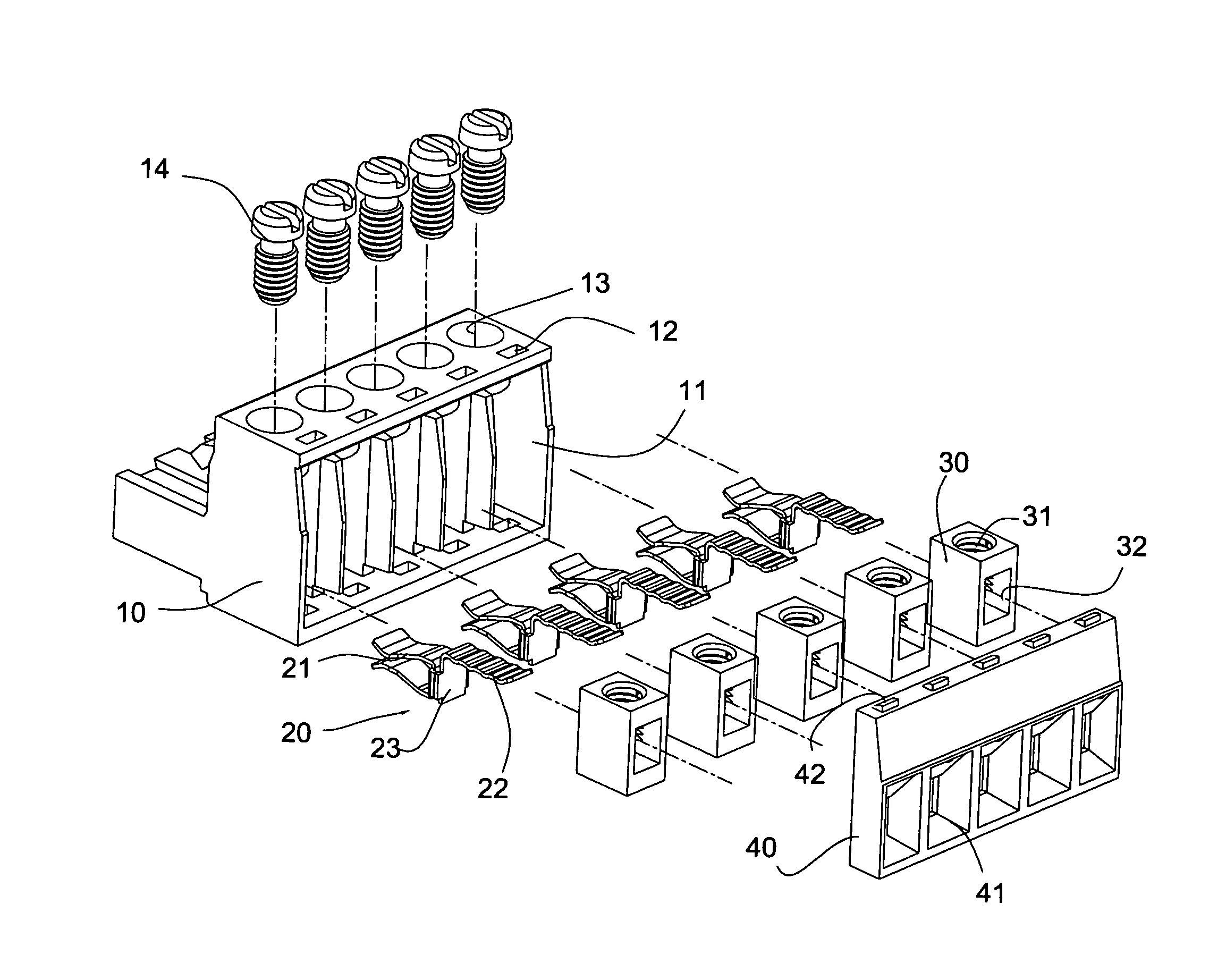
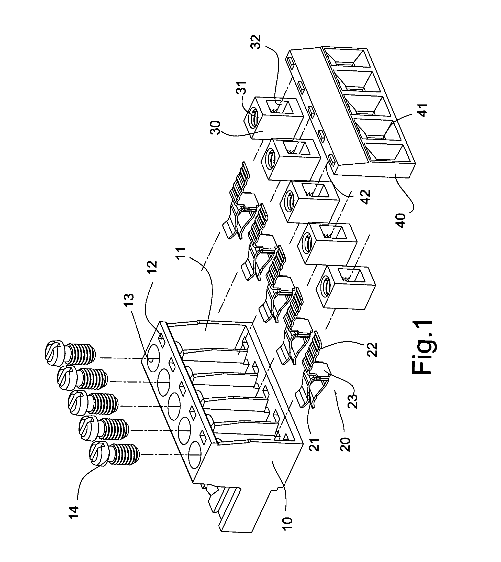
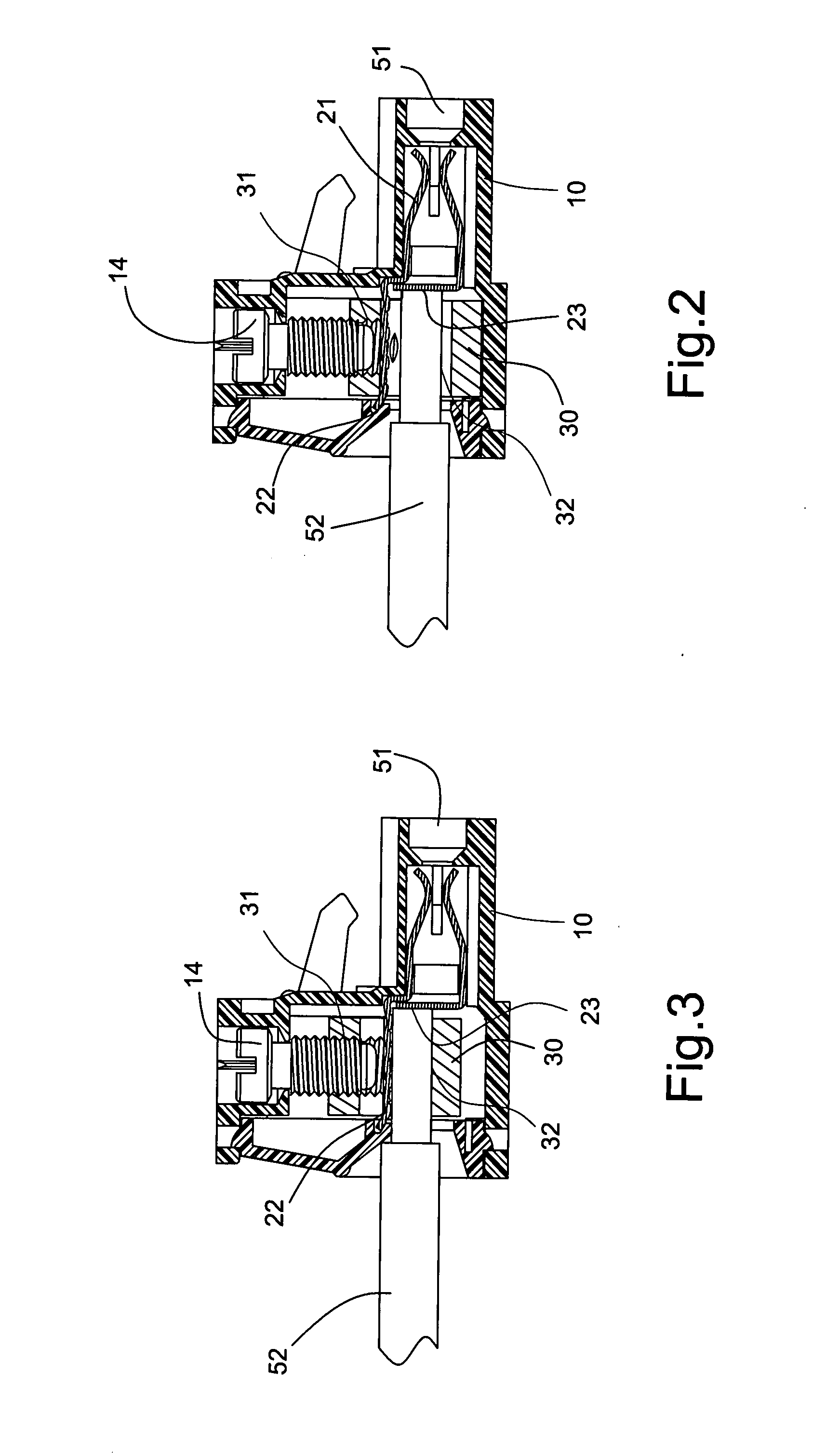
[0011]Referring to FIG. 1, a terminal table fastener in accordance with the present invention comprises a housing 10, at least a resilient terminal 20, at least a fixing element 30 and at least a screw element 14. At least a chamber 11 is defined through the housing 10. A rectangular hole 12 and a circular hole 13 are respectively defined in the housing 10 and communicate with the chamber 11. Each resilient terminal 20 forms a clamp 21 at a rear end thereof for retaining a terminal wire 51 (shown in FIGS. 2 and 3), and a touch plate 22 at a front end thereof. An abutting portion 23 is formed between the clamp 21 and the touch plate 22 for abutting against the fixing element 30. Each fixing element 30 defines a through hole 32 through a front face and a rear face thereof. In assembly, the abutting portion 23 extends into the through hole 32 of the fixing element 30 to electrically contact a circuit wire 52 (shown in FIGS. 2 and 3). Each fixing element 30 further defines a screw hole ...


PUM


Abstract

A terminal table fastener is provided which includes a housing, a fixing element, a resilient terminal and a screw element. The housing defines at least a chamber therein. The fixing element is inserted into the chamber, and the screw element screws to the fixing element for elevating the fixing element. A through hole is defined in the fixing element for accommodating a circuit wire. The resilient terminal is received in the chamber, and is inserted into the through hole for electrically contacting the circuit wire. The fixing element is integrally formed by forging iron and is heat processed to be seamless, and thus has high rigidity and large torque. The screw element extends into the through hole to press the circuit wire and the resilient terminal. The fixing element is elevated to clamp the circuit wire. The terminal table fastener therefore has optimal retention and effective electrical conduction.

Description

BACKGROUND OF THE INVENTION[0001](a) Field of the Invention[0002]The present invention relates to a terminal table fastener, and particularly to a terminal table fastener used for connecting a circuit wire with a terminal wire on a terminal table.[0003](b) Description of the Prior Art[0004]Terminal tables are popularly applied to circuit boards or other electronic appliances for transferring signals of a main board or a machine or receiving external signals. In prior art, a circuit wire is connected with a terminal. A hollow fastener is lifted by screws to make the circuit wire contact a touch plate.[0005]The hollow fastener is so vital for connection between the circuit wire and the touch plate. Larger contact area of the circuit wires have, or closer the circuit wires are to the touch plate, lower impedance of the circuit has, and therefore more optimal transmission characteristics is achieved. An ordinary fastener is formed by stamping an iron sheet, often producing a slit. Durin...

Claims


Application Information

Patent Timeline
Patent Type & Authority Applications(United States)
IPC IPC(8): H01R9/22
CPCH01R4/38H01R12/515H01R9/24
Inventor YEH, SHENG-HSING
Owner ANYTEK TECH CORP LTD
Why Eureka
Try Eureka