
Storage system

a storage system and data technology, applied in the field of storage systems, can solve the problems of high-capacity storage systems, data to be stored has increased day by day, and data storage is required. achieve the effect of efficient and quick data restoration

Inactive Publication Date: 2011-12-01
NEC CORP +1
View PDF9 Cites 35 Cited by
  • Summary
  • Abstract
  • Description
  • Claims
  • Application Information

AI Technical Summary

Benefits of technology

[0014]Accordingly, an object of the present invention is to provide a storage system that can increase efficiency of processing in data restoration and inhibit system load and processing delay.
[0019]With the configurations as described above, the present invention can realize efficient and quick data restoration.

Problems solved by technology

Because data to be stored has increased day by day and the amount thereof has become huge, a high-capacity storage system is required.
However, as described above, in a case that a storage system has a function of distributing by considering the load of each node autonomously, relocation of data may become inefficient at the time of restoration from a node fault.
Consequently, unnecessary data regeneration or movement may be performed, and relocation of data at the time of restoration becomes inefficient, which may increase load of the system and cause processing delay.

Method used


Image

  • Storage system
  • Storage system
  • Storage system

Examples


first exemplary embodiment

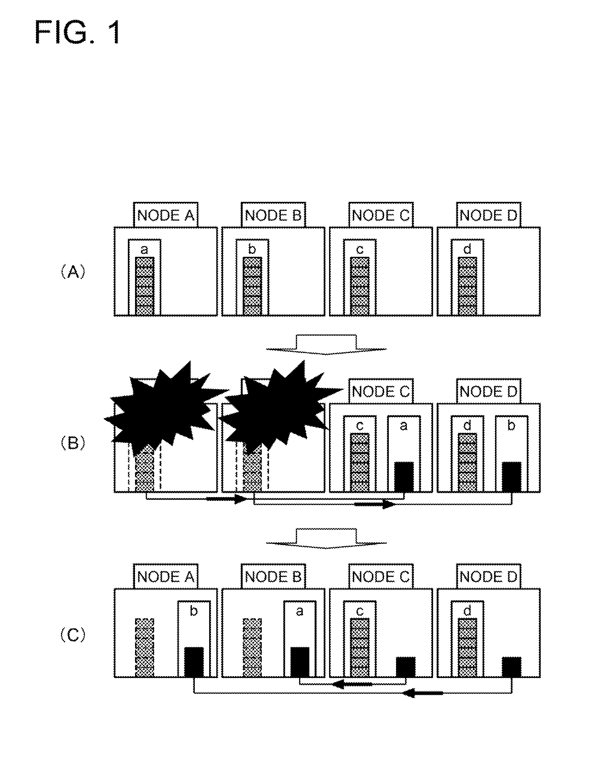
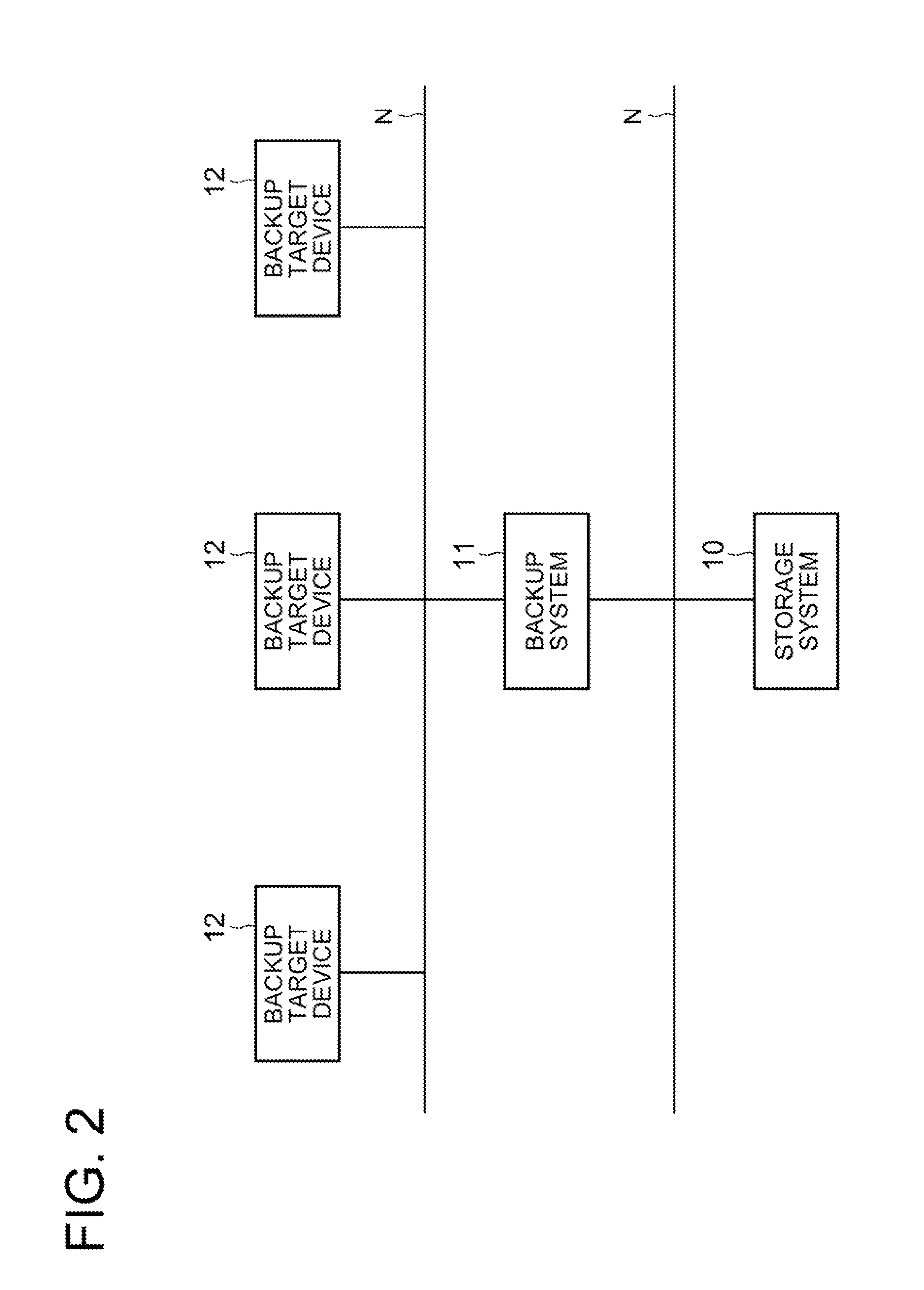
[0032]A first exemplary embodiment of the present invention will be described with reference to FIGS. 2 to 11. FIG. 2 is a block diagram showing a configuration of a whole system. FIG. 3 is a block diagram schematically showing a storage system, and FIG. 4 is a function block diagram showing a configuration. FIGS. 5 and 6 are explanation views for explaining an operation of the storage system. FIGS. 7A and 7B are views each showing an example of data acquired and stored in the storage system. FIGS. 8A, 8B, 9 and 10 are flowcharts each showing an operation by the storage system. FIGS. 11A to 11C are views each showing an aspect of return of data in the storage system.

[0033]This exemplary embodiment shows a specific example of a storage system disclosed in a second exemplary embodiment described later. Below, a case of configuring the storage system by connecting a plurality of server computers will be described. However, the storage system of the present invention is not limited to b...

second exemplary embodiment

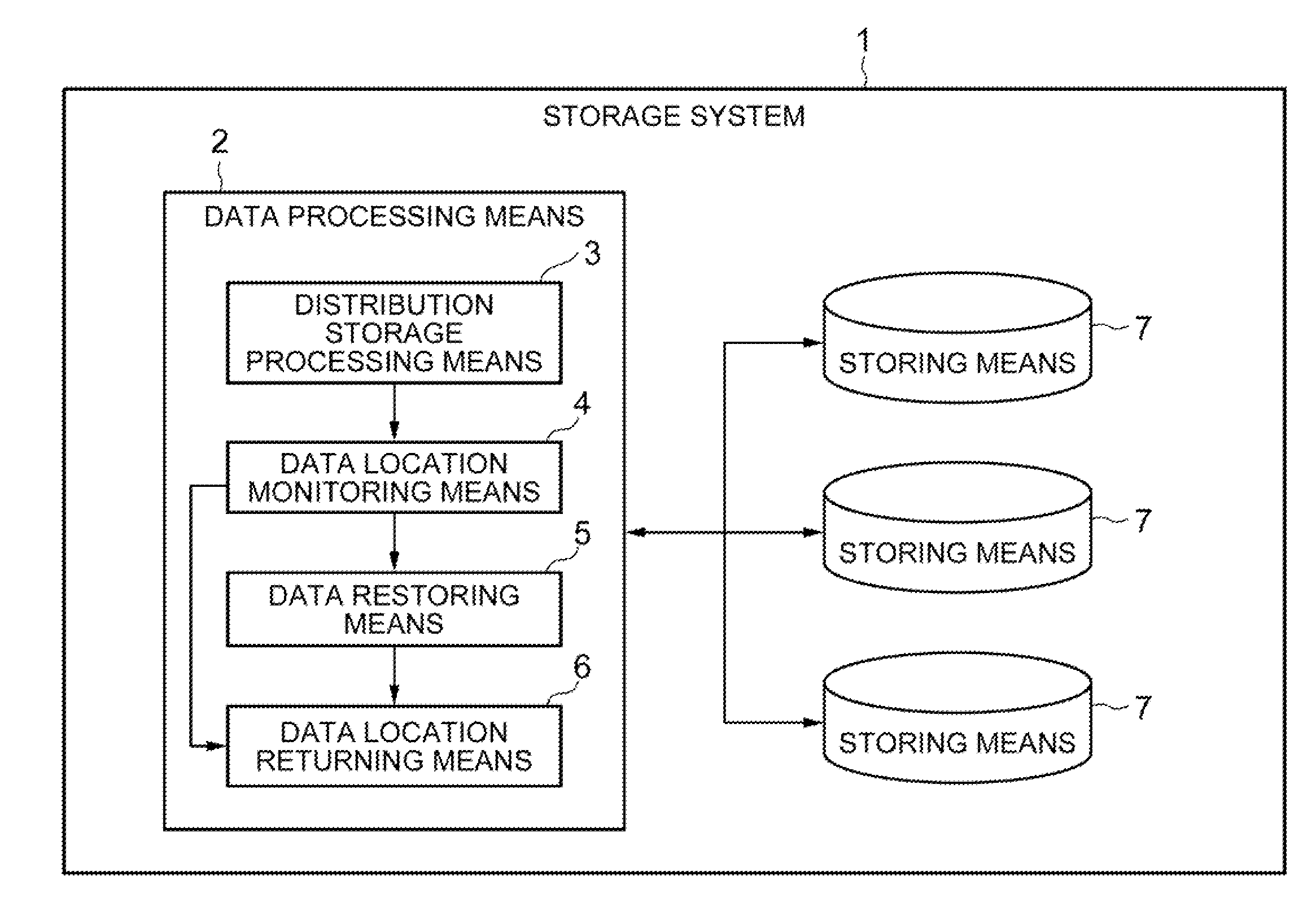
[0065]A second exemplary embodiment of the present invention will be described with reference to FIG. 12. FIG. 12 is a function block diagram showing a configuration of a storage system. In this exemplary embodiment, a basic configuration and operation of the storage system will be described.

[0066]As shown in FIG. 12, a storage system of this exemplary embodiment includes a plurality of storing means 7 and a data processing means 2 configured to store data into the plurality of storing means 7 and retrieve the data stored in the storing means.

[0067]Then, the data processing means 2 includes: a distribution storage processing means 3 configured to distribute and store a plurality of fragment data composed of division data obtained by dividing storage target data into plural pieces and redundant data for restoring the storage target data, into the plurality of storing means; a data location monitoring means 4 configured to monitor a data location status of the fragment data in the res...


PUM


Abstract

A storage system includes: a distribution storage processing means configured to distribute and store a plurality of fragment data into a plurality of storing means; a data location monitoring means configured to monitor a data location status of the fragment data and store data location information representing the data location status; and a data restoring means configured to, when the storing means is down, regenerate the fragment data having been stored in the down storing means based on the fragment data stored in the other storing means. The storage system also includes: a data location returning means configured to, when the down storing means recovers, return a data location of the fragment data by using the fragment data stored in the storing means having recovered so that the data location status becomes as represented by the data location information stored by the data location monitoring means.

Description

TECHNICAL FIELD[0001]The present invention relates to a storage system, and specifically, relates to a storage system that distributes and stores data into a plurality of storage devices.BACKGROUND ART[0002]In recent years, as computers have developed and become popular, various kinds of information are put into digital data. As a device for storing such digital data, there is a storage device such as a magnetic tape and a magnetic disk. Because data to be stored has increased day by day and the amount thereof has become huge, a high-capacity storage system is required. Moreover, it is required to keep reliability while reducing the cost for storage devices. In addition, it is required that data can easily be retrieved later. As a result, such a storage system is desired that is capable of automatically realizing increase of the storage capacity and performance thereof, that eliminates a duplicate of storage to reduce the cost for storage, and that has high redundancy.[0003]Under su...

Claims


Application Information

Patent Timeline
IPC IPC(8): G06F12/16
CPCG06F2211/1028G06F11/1088G06F11/1084
Inventor NODA, KENJITOKUTAKE, HIROYUKI
Owner NEC CORP
Learn More