Image Forming Apparatus and Image Forming Method Having Power Saving Mode

a technology of image forming apparatus and power saving mode, which is applied in the direction of electrographic process, instruments, sustainable buildings, etc., can solve the problems of low power saving and possible read disturb errors in the controller program, and achieve the effect of avoiding read disturb errors and high power saving

Active Publication Date: 2011-12-01
KYOCERA DOCUMENT SOLUTIONS INC
View PDF5 Cites 21 Cited by
  • Summary
  • Abstract
  • Description
  • Claims
  • Application Information

AI Technical Summary

Benefits of technology

[0014]The present disclosure relates to an image forming apparatus and an image forming method that may have a higher degree of power saving and that may avoid read disturb errors even when frequently switching between a sleep status mode and a normal status mode.

Problems solved by technology

Therefore, this results in low power saving.
Accordingly, if switching between the sleep state mode and the normal status mode frequently occurs, a read disturb error may possibly occur in the controller program.

Method used


Image

  • Image Forming Apparatus and Image Forming Method Having Power Saving Mode
  • Image Forming Apparatus and Image Forming Method Having Power Saving Mode
  • Image Forming Apparatus and Image Forming Method Having Power Saving Mode

Examples


first embodiment

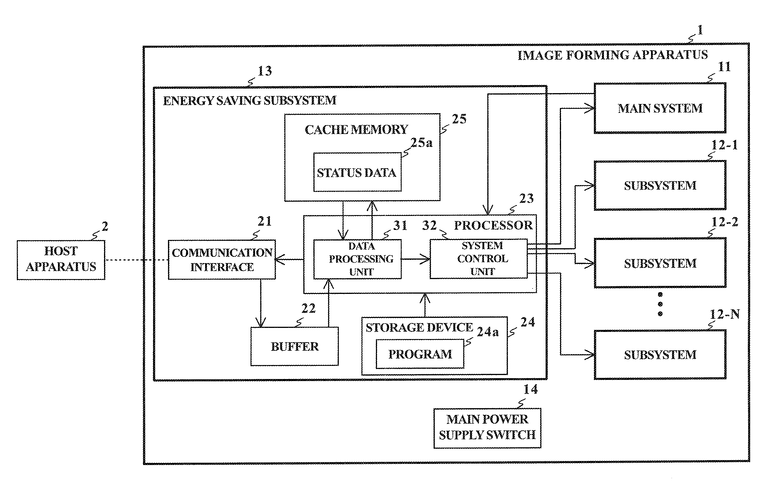
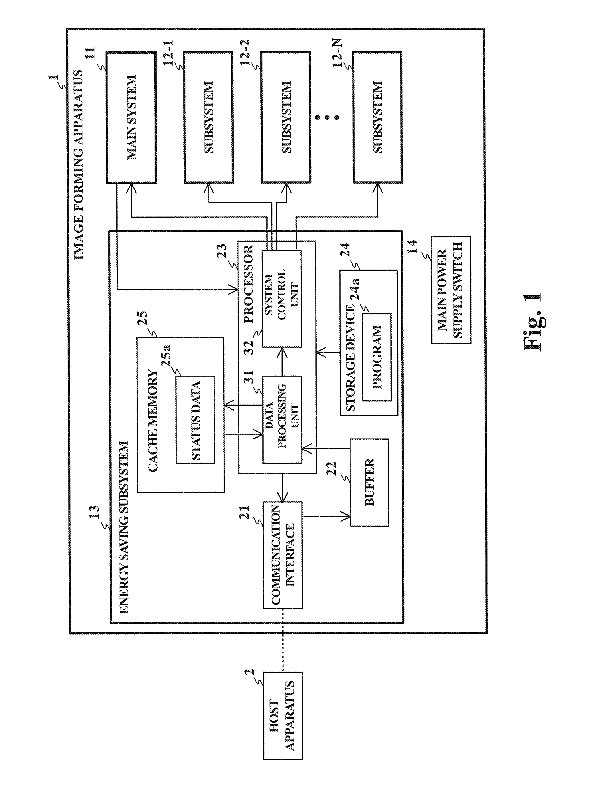
[0026]FIG. 1 shows a block diagram showing an example of a configuration of an image forming apparatus according to an embodiment of the present disclosure. An image forming apparatus 1 includes, for example, a printer or a multifunction peripheral (MFP). A host apparatus 2, such as a personal computer, is connected to the image forming apparatus 1. The image forming apparatus 1 receives data from the host apparatus 2 and processes the received data.

[0027]The image forming apparatus 1 includes a main system 11, one or more subsystems 12-1 to 12-N, and an energy saving subsystem 13.

[0028]The main system 11 controls the subsystems to perform various processes. The subsystems 12-1 to 12-N perform a function (for example, a printer function, a scanner function, a facsimile communication function, a user interface function of an operation panel) of the image forming apparatus 1. The energy saving subsystem 13 receives data from the host apparatus 2 and switches operation status modes of ...

second embodiment

[0060]FIG. 3 shows a block diagram illustrating an example of the configuration of the main system 11 in the image forming apparatus 1. The main system 11 includes a ROM 210, a non-volatile memory 220, a RAM 230, and a micro processor unit (MPU) 240.

[0061]The ROM 210 is a non-rewritable non-volatile memory. A boot program 310 may be stored in the ROM 210 in the second embodiment. The boot program 310 is executed by the MPU 240 to boot a controller program 320 when the main system 11 is started (that is, the main system 11 is turned on).

[0062]The non-volatile memory 220 is a rewritable non-volatile memory, such as a NAND flash memory, in which a read disturb error may possibly occur. The controller program 320, a recovery program 330, and a counter 340 may be stored in the non-volatile memory 220 in the second embodiment.

[0063]The controller program 320 is used to control the subsystems 12-1 to 12-N and to perform the internal processing in the main system 11.

[0064]The controller pro...


PUM


Abstract

An image forming apparatus includes a communication interface receiving data; a buffer storing the data; a main system processing the stored data; a subsystem controlled by the main system to perform a function of the image forming apparatus; a system control unit; and a data processing unit. The system control unit switches an operation status mode of the image forming apparatus between a normal status mode and a deep sleep status mode. When the image forming apparatus is in the deep sleep status mode, the data processing unit processes the data received from the buffer if the data is determined to be processable by the data processing unit and causes the system control unit to switch the operation status mode from the deep sleep status mode to the normal status mode if the received data is determined not to be processable by the data processing unit.

Description

INCORPORATION BY REFERENCE[0001]This application is based upon and claims the benefit of priority from corresponding Japanese Patent Application Nos. 2010-122930 filed May 28, 2010, 2010-242015 filed Oct. 28, 2010, 2011-004637 filed Jan. 13, 2011, 2011-021199 filed Feb. 2, 2011, and 2011-084530 filed Apr. 6, 2011, the entire contents of which is incorporated herein by reference.BACKGROUND[0002]1. Field of the Invention[0003]The present invention relates to an image forming apparatus and an image forming method having a power saving mode.[0004]2. Description of the Related Art[0005]Some typical image forming apparatuses, such as printers, copiers, and multifunction peripherals (MFP), have a power saving mode (sleep status mode).[0006]The typical image forming apparatus decreases the reception speed of data upon receiving the data in the sleep status mode, and then starts a reception process of the data with the start of an initialization process for returning to a normal status mode....

Claims


Application Information

Patent Timeline
Patent Type & Authority Applications(United States)
IPC IPC(8): G06F1/32
CPCG03G15/5004G06F1/3284Y02B60/1282Y02B60/1267G06F1/3287Y02D10/00
Inventor OKUDA, MASAYA
Owner KYOCERA DOCUMENT SOLUTIONS INC
Why Eureka
Try Eureka