Rolling cutter assembled directly to the bit pockets

a technology of rolling cutters and bit pockets, which is applied in the direction of earth-moving drilling tools, construction, metal-working drilling tools, etc., can solve the problems of cutter failure, drill bit failure, and bit and pdc cutters being subjected to substantial abrasion forces during drilling operations,

Active Publication Date: 2011-12-08
SMITH INT INC
View PDF6 Cites 92 Cited by
  • Summary
  • Abstract
  • Description
  • Claims
  • Application Information

AI Technical Summary

Benefits of technology

[0021]In another aspect, embodiments of the present disclosure relate to a drill bit having a bit body; a plurality of blades extending radially from the bit body, wherein each blade has a leading face and a trailing face; a plurality of cutter pockets disposed on the plurality of blades; at least one rolling cutter, wherein each rolling cutter is disposed in one of the cutter pockets, and wherein each rolling cutter comprises a substrate and a cutting face; and at least one blocker, wherein each blocker covers a portion of the cutting face of one or more rolling cutters.

Problems solved by technology

Additionally, the bit and the PDC cutters may be subjected to substantial abrasive forces.
In some instances, impact, vibration, and erosive forces have caused drill bit failure due to loss of one or more cutters, or due to breakage of the blades.
Without proper flow characteristics, insufficient cooling of the cutters 150 may result in cutter failure during drilling operations.
Conventional PCD is stable at temperatures of up to 700-750° C., after which observed increases in temperature may result in permanent damage to and structural failure of PCD.
In particular, heat caused by friction between the PCD and the work material causes thermal damage to the PCD in the form of cracks, which lead to spalling of the diamond layer and delamination between the diamond layer and substrate.
This deterioration in PCD is due to the significant difference in the coefficient of thermal expansion of the binder material, which is typically cobalt, as compared to diamond.
Upon heating of PCD, the cobalt and the diamond lattice will expand at different rates, which may cause cracks to form in the diamond lattice structure and result in deterioration of the PCD.
High operating temperatures may also lead to back conversion of the diamond to graphite causing loss of microstructural integrity, strength loss, and rapid abrasive wear.
However, some of the problems described above that plague PCD cutting elements, i.e., chipping, spalling, partial fracturing, cracking or exfoliation of the cutting table, are also often encountered in TSP cutters or other types of cutters having an ultra hard diamond-like cutting table such as polycrystalline cubic boron nitride (PCBN) bonded on a cemented carbide substrate.
In particular, it has been observed that TSP cutters are slightly more prone to spalling and delamination under severe loads.
These problems result in the early failure of the cutting table and thus, in a shorter operating life for the cutter.
Over time, the edge of the cutting surface that constantly contacts the formation begins to wear down, forming a local wear flat, or an area worn disproportionately to the remainder of the cutting element.
Local wear flats may result in longer drilling times due to a lose of rate of penetration caused by dulling of edge of the cutting element.
As a result, heat builds up along the cutting surface, and results in cutting insert fracture.
When a cutting element breaks, the drilling operation may sustain a loss of rate of penetration, and additional damage to other cutting elements, should the broken cutting element contact a second cutting element.

Method used


Image

  • Rolling cutter assembled directly to the bit pockets
  • Rolling cutter assembled directly to the bit pockets
  • Rolling cutter assembled directly to the bit pockets

Examples


Embodiment Construction

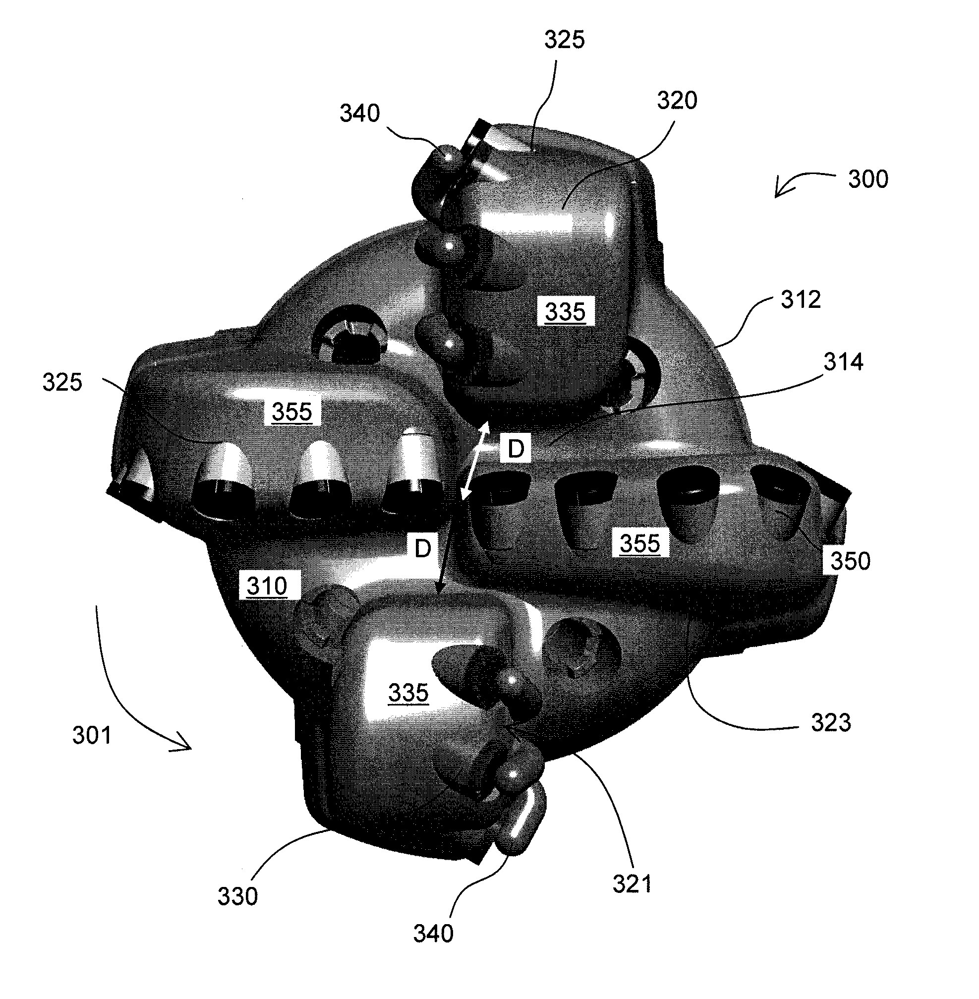
[0046]Drill bits according to embodiments of the present disclosure and methods for forming such drill bits are described below. According to some embodiments of the present disclosure, a drill bit has at least one rolling cutter and a blocker positioned adjacent to each rolling cutter. Rolling cutters of the present disclosure may be used on downhole cutting tools including, for example, drag bits and hybrid drill bits.

[0047]A rolling cutter, as referred to herein, is a cutting element having at least one surface that may rotate within a cutter pocket as the cutting element contacts the drilling formation. As the cutting element contacts the formation, shearing may allow a portion of the cutting element to rotate around a cutting element axis extending through a central plane of the cutting element. Rolling cutters according to the present disclosure are retained within the cutter pocket by a blocker. As used herein, a blocker is a component separate from the bit that is attached t...


PUM

PropertyMeasurementUnit
side rake angleaaaaaaaaaa

Abstract

A drill bit having a bit body, a plurality of blades extending radially from the bit body, a plurality of cutter pockets disposed on the plurality of blades, at least one rolling cutter disposed in one of the cutter pockets, wherein each rolling cutter has a substrate, a cutting face, a cutting edge, and a side surface, and at least one blocker positioned adjacent to each of the at least one rolling cutters on a leading face of the blade, wherein each blocker has a retention end and an attachment end is disclosed. The retention end of each blocker is positioned adjacent to a portion of the cutting face of each rolling cutter to retain the rolling cutter in the cutter pocket and the attachment end is attached to a portion of the blade.

Description

CROSS-REFERENCE TO RELATED APPLICATIONS[0001]Pursuant to 35 U.S.C. §119, this Application claims the benefit of U.S. Provisional Application 61 / 351,035 filed on Jun. 3, 2010, which is herein incorporated by reference in its entirety.BACKGROUND OF INVENTION[0002]Various types and shapes of earth boring bits are used in various applications in the earth drilling industry. Earth boring bits have bit bodies which include various features such as a core, blades, and cutter pockets that extend into the bit body or roller cones mounted on a bit body, for example. Depending on the application / formation to be drilled, the appropriate type of drill bit may be selected based on the cutting action type for the bit and its appropriateness for use in the particular formation.[0003]Drag bits, often referred to as “fixed cutter drill bits,” include bits that have cutting elements attached to the bit body, which may be a steel bit body or a matrix bit body formed from a matrix material such as tungs...

Claims


Application Information

Patent Timeline
Patent Type & Authority Applications(United States)
IPC IPC(8): E21B10/36B23P15/28
CPCE21B10/633B23P15/28
Inventor SHEN, YUELINZHANG, YOUHEBURHAN, YURISIRACKI, MICHAEL A.NAGARAJ, MAHAVIRDURAIRAJAN, BALAMCDONOUGH, SCOTT D.CARIVEAU, PETER THOMAS
Owner SMITH INT INC
Why Eureka
Try Eureka