

Integrated Electric Motor and Gear in an Aircraft Wheel
- Summary
- Abstract
- Description
- Claims
- Application Information
AI Technical Summary
Benefits of technology
Problems solved by technology
Method used
Image

Examples
Embodiment Construction
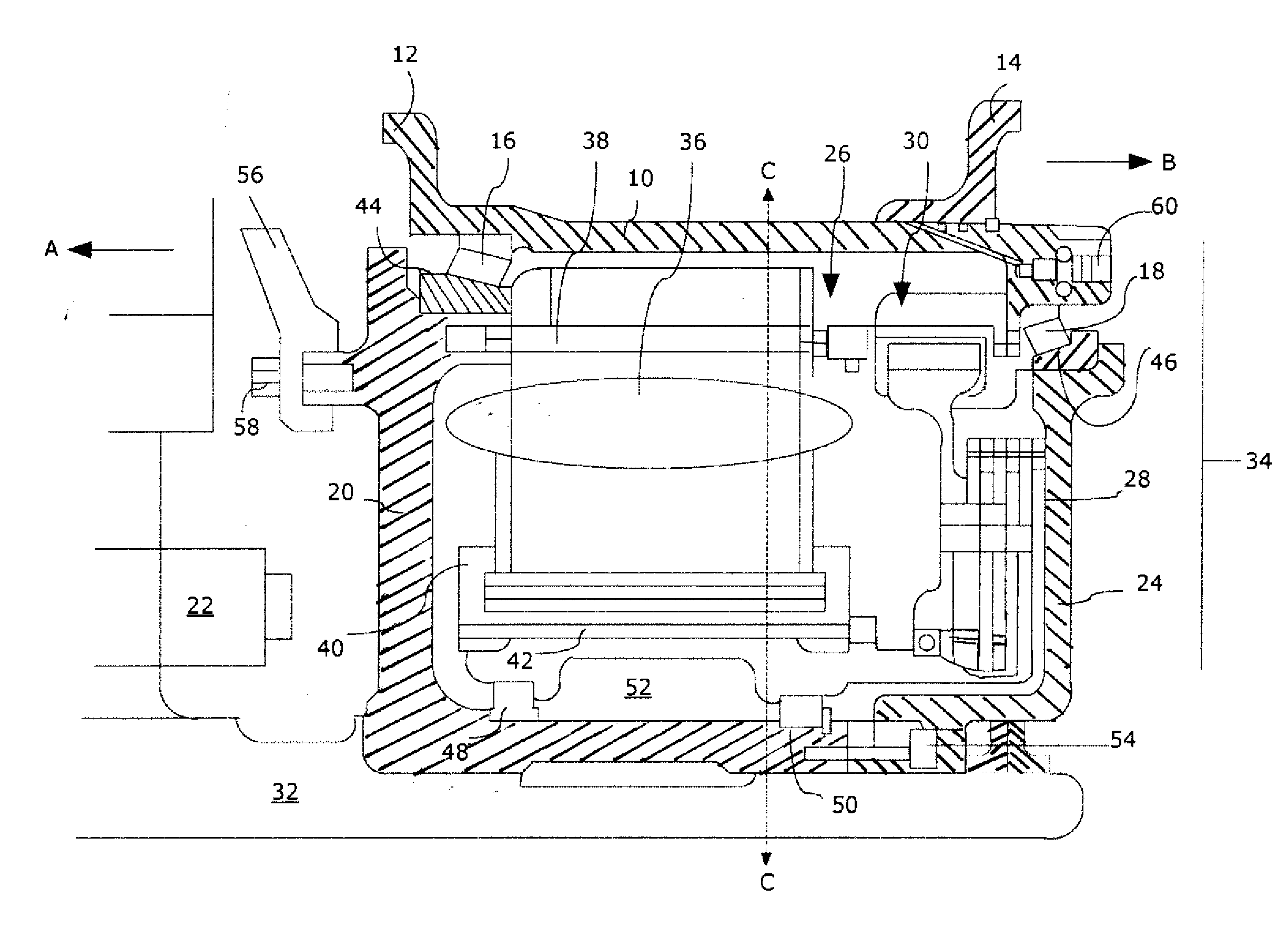
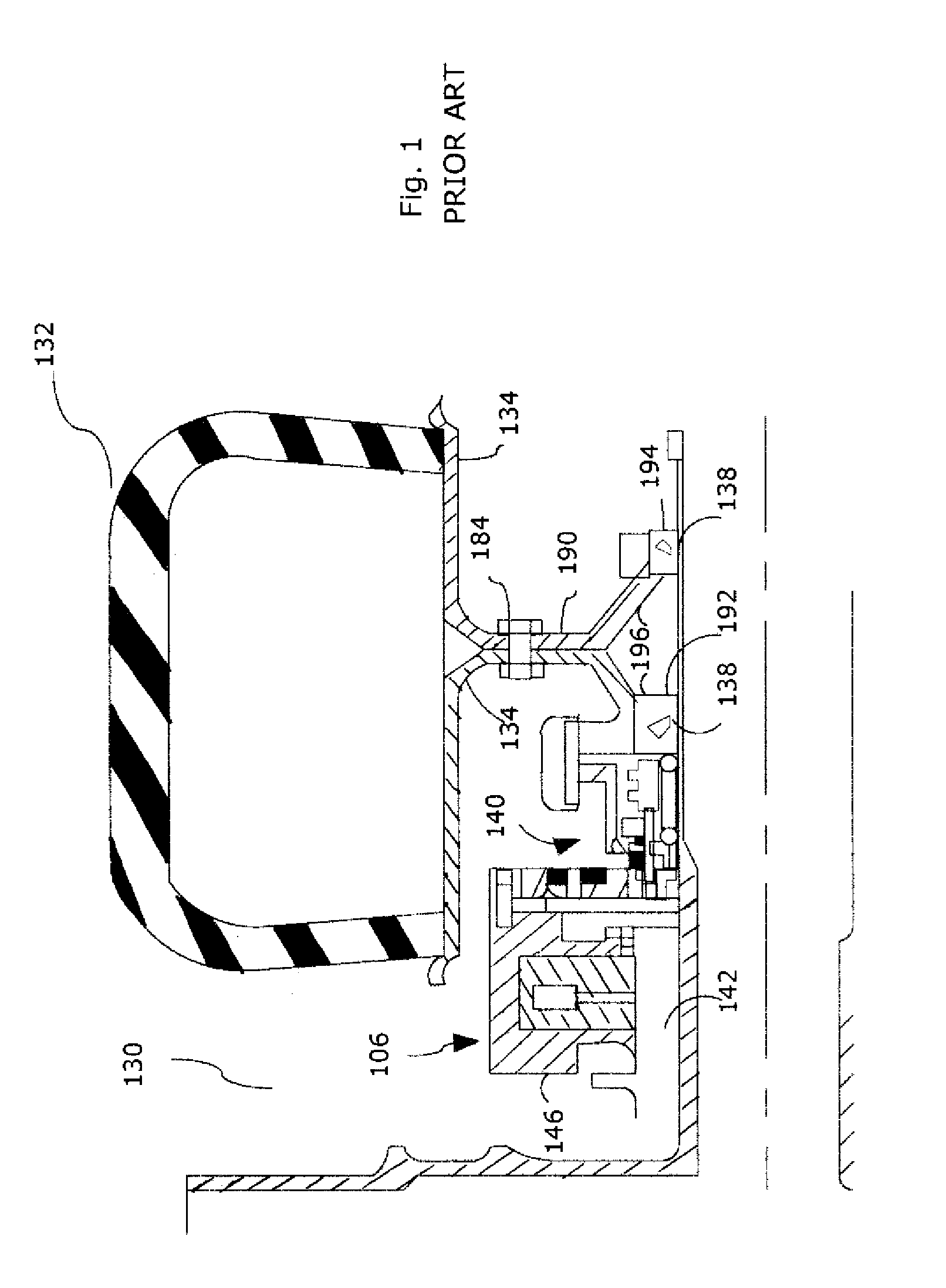
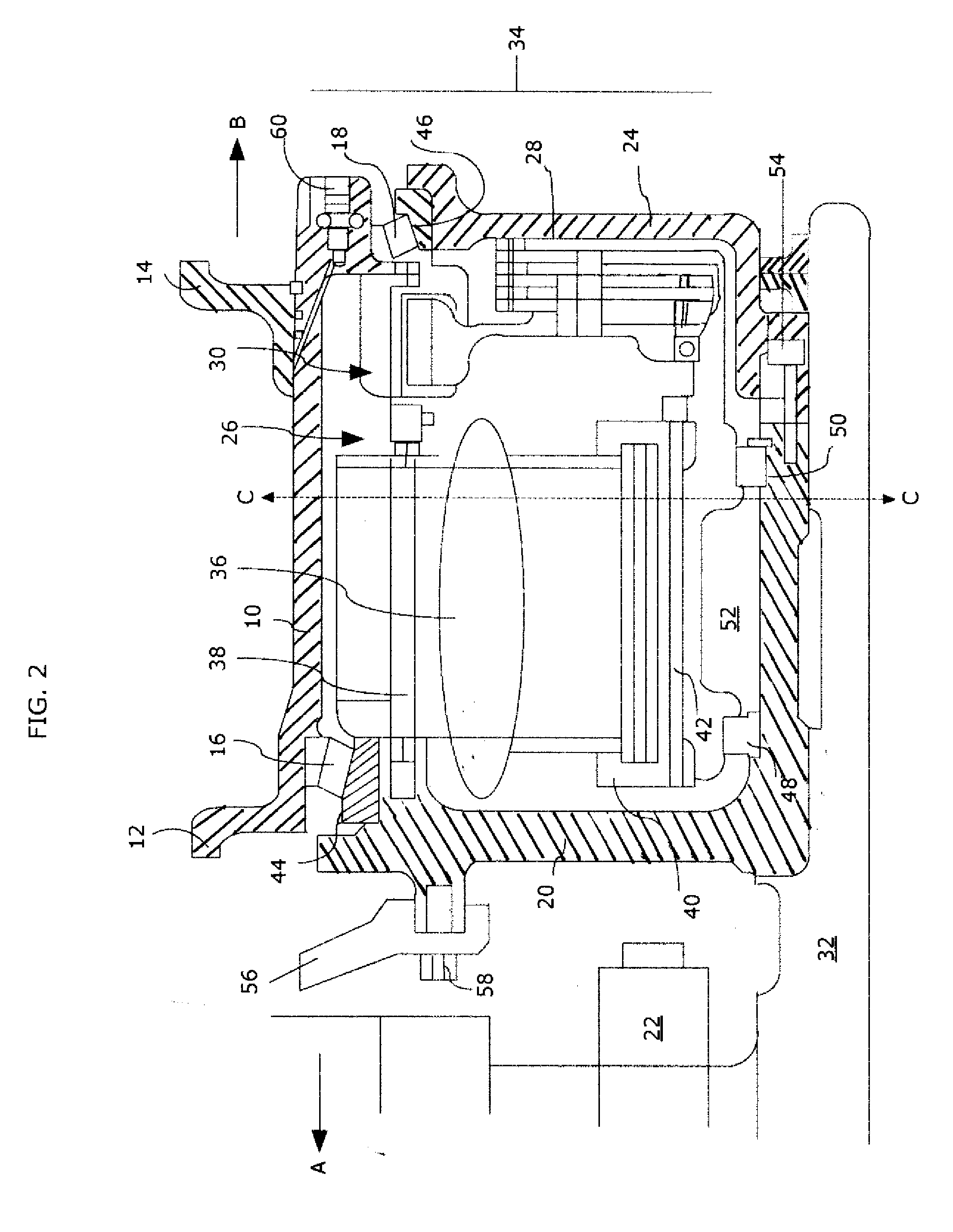
[0024]The many advantages of being able to drive an aircraft on the ground independently without using the aircraft main engines, as discussed above, have been acknowledged. Integrating a motor and gear assembly, within an aircraft gear wheel as the aircraft is being constructed does not present problems because the space available for landing gear components, including motors for driving gear wheels, can be adjusted as required. Retrofitting existing aircraft presents challenges, however. Because of the unique configuration of the wheel, the integral wheel and geared motor assembly of the present invention overcomes these challenges and provides a wheel and geared motor assembly that can be fitted into the limited space available for aircraft landing gear components without modifying any of the other landing gear components. As a result, an aircraft's existing wheel well, tire, axle, piston, and other landing gear components can be used with this integrated wheel and geared motor a...
PUM
 Abstract
Description
Claims
Application Information