
Operation device and image reading apparatus

Active Publication Date: 2011-12-08
CANON KK
View PDF1 Cites 26 Cited by
  • Summary
  • Abstract
  • Description
  • Claims
  • Application Information

AI Technical Summary

Benefits of technology

[0015]The present invention is directed to an apparatus capable of illuminating a large illumination target region having a ring-like shape, such as a ring-shaped touch switch, from behind and with unevenness of brightness suppressed to a minimum, and with as small a number of light sources as possible.

Problems solved by technology

The above-described structure of the conventional operation unit may not be implemented if uneven luminosity occurs and if a large number of light sources are required.
However, in order to illuminate the necessary range of a large area with light by using the smallest possible number of light sources, the structure of the operation unit discussed in Japanese Patent Application Laid-Open No. 11-283425 may not be useful enough.
Therefore, it becomes difficult to uniformly illuminate the entire device with highly bright light.
Accordingly, the arrangement of the light sources or the device itself may be restricted.
In addition, the costs of manufacture may increase.
Furthermore, it may be difficult to apply the illumination device discussed in Japanese Patent Application Laid-Open No. 11-283425 as a backlight for illuminating the capacitance touch switch discussed in the U.S. Patent Application Publication No. 2009 / 0033636 A1 with light because of the following reason.
If air gap exists between the surface of a touch panel, which is touched by an operator with his finger, and an electrode, it may become difficult to detect the capacitance.
Therefore, the electrode may interfere with the light emitted from the backlight and may overlap on the display.
Accordingly, in this case, the display may not be appropriately executed.

Method used


Image

  • Operation device and image reading apparatus
  • Operation device and image reading apparatus
  • Operation device and image reading apparatus

Examples


Embodiment Construction

[0025]Various exemplary embodiments, features, and aspects of the invention will be described in detail below with reference to the drawings.

[0026]In the present specification, apparatuses which have an image reading unit configured to read an image of a document, such as a scanner, a printer, a facsimile apparatus, a copying machine, or a multifunction peripheral (MFP), will be collectively referred to as an “image reading apparatus”.

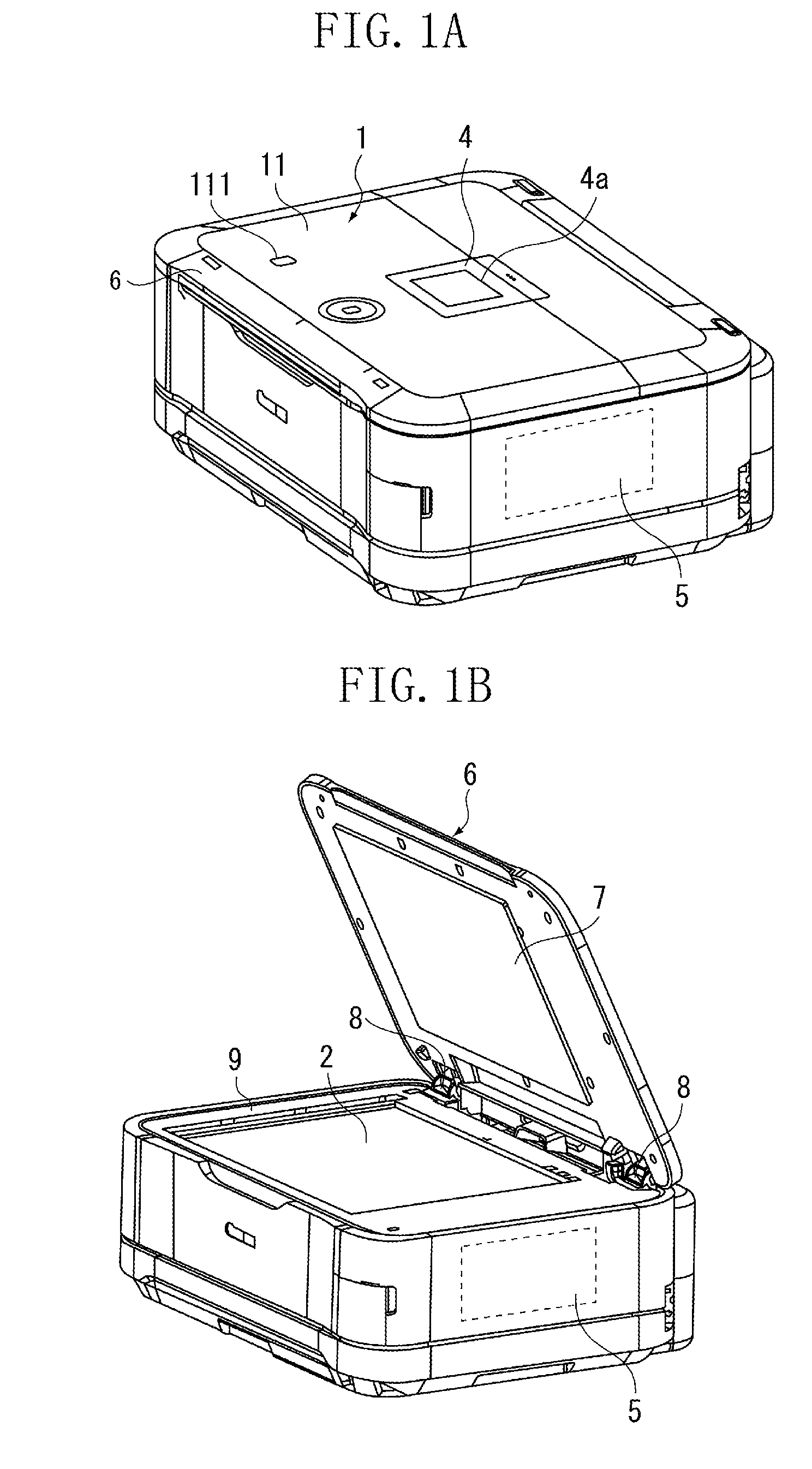
[0027]FIGS. 1A and 1B illustrate an exemplary configuration of an image reading apparatus according to an exemplary embodiment of the present invention. FIG. 1A illustrates a state of the image reading apparatus in which a pressure plate thereof is closed while in FIG. 1B, the pressure plate is opened.

[0028]The image reading apparatus, within a housing thereof, includes a reading unit having a flatbed scanner, a recording unit, and a control unit 5. The recording unit reads an image of a document set on a document reading surface. The recording unit pr...


PUM


Abstract

A touch panel includes a ring-like shaped light-transmissive portion. A ring-shaped diffusion surface is formed on the bottom surface of a light guide element. The ring-like shape includes a second region provided at a location corresponding to two light sources adjacent to a first region corresponding to one light source. A distance from a location of the ring-shaped light-transmissive portion to a periphery of the ring close to the light source is greater in the second region than in the first region. Light emitted from the light source and incident to the light guide element is diffusion-reflected on the diffusion surface and a part of the diffusion-reflected light illuminates the light-transmissive portion.

Description

BACKGROUND OF THE INVENTION[0001]1. Field of the Invention[0002]The present invention generally relates imaging and, more particularly, to an operation device including a touch switch and an image processing apparatus including the operation device.[0003]2. Description of the Related Art[0004]Japanese Patent Application Laid-Open No. 2009-88759 discusses a multifunction peripheral (MFP) which includes an image reading unit. The device includes a reading unit, which is configured to read an image of a document set on a document reading surface, and a pressing plate, which can open on the document reading surface. On a top surface of the pressing plate, an operation unit, which includes a plurality of input keys, and a display device, such as a liquid crystal display (LCD) panel, are provided.[0005]U.S. Patent Application Publication No. 2009 / 0033636 A1 discusses a capacitive touch panel input device. The capacitive touch panel input device includes a substrate and a spacer. A plurali...

Claims


Application Information

Patent Timeline
IPC IPC(8): H04N1/32F21V8/00
CPCG02B6/001H03K17/962H03K2217/94042H03K2217/96079H04N2201/0094H04N1/00411H04N1/0049H04N2201/0081H04N1/00384
Inventor ISHIDA, YASUSHIOGUSHI, HIROSHISHIMOYAMA, NOBORU
Owner CANON KK
Learn More