
Apparatus and method for imaging subsurface structure

Inactive Publication Date: 2011-12-08
SHINS GEOPHYSICS
View PDF0 Cites 29 Cited by
  • Summary
  • Abstract
  • Description
  • Claims
  • Application Information

AI Technical Summary

Benefits of technology

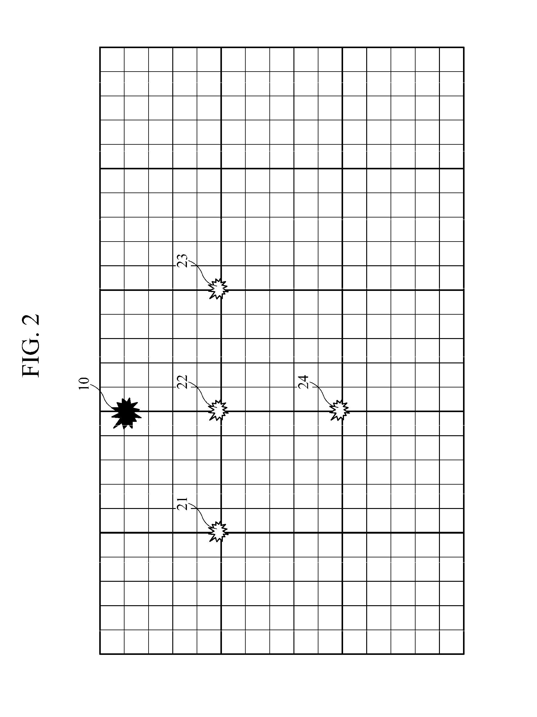
[0010]Therefore, since a large grid is adopted by using, instead of a real source, an equivalent source that is at least one source located at a coarse-grid point, the amount of calculation for imaging a subsurface structure by modeling a wave equation in the Laplace domain can be significantly reduced. That is, an equivalent source on a large grid is used to model a wavefield by a source near the surface of the water.
[0011]Moreover, an equivalent source vector can be easily obtained by multiplying an analytical solution vector by an impedance matrix of a Laplace-domain wave equation, wherein the analytical solution vector is obtained from an analytical solution of a Laplace-domain wave equation in a homogeneous half space by the real source.

Problems solved by technology

However, using such a large grid (a coarse grid) is actually impossible due to the Dirichlet boundary condition.
However, since air guns, actual sources that are generally used in seismic marine survey, are located in the range of 5-20 m (generally, 10 m or less) away from the surface of the water, the source problem makes it actually impossible to achieve the advantage of using a large grid size in the technology is of imaging the subsurface structure by modeling a wave equation in the Laplace domain.

Method used


Image

  • Apparatus and method for imaging subsurface structure
  • Apparatus and method for imaging subsurface structure
  • Apparatus and method for imaging subsurface structure

Examples


Embodiment Construction

[0016]The following description is provided to assist the reader in gaining a comprehensive understanding of the methods, apparatuses, and / or systems described herein. Accordingly, various changes, modifications, and equivalents of the methods, apparatuses, and / or systems described herein will be suggested to those of ordinary skill in the art. Also, descriptions of well-known functions and constructions may be omitted for increased clarity and conciseness.

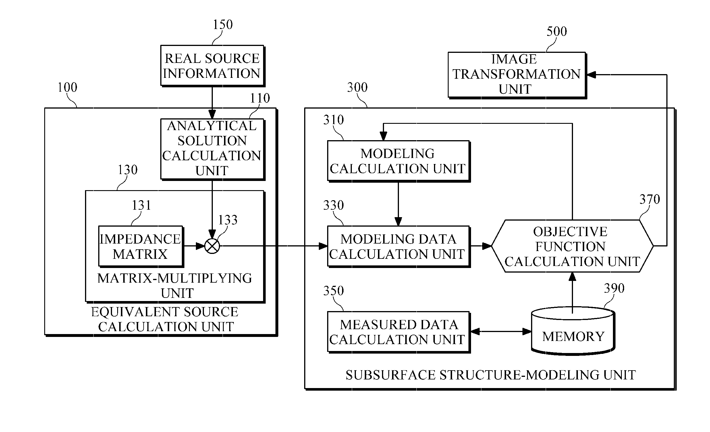
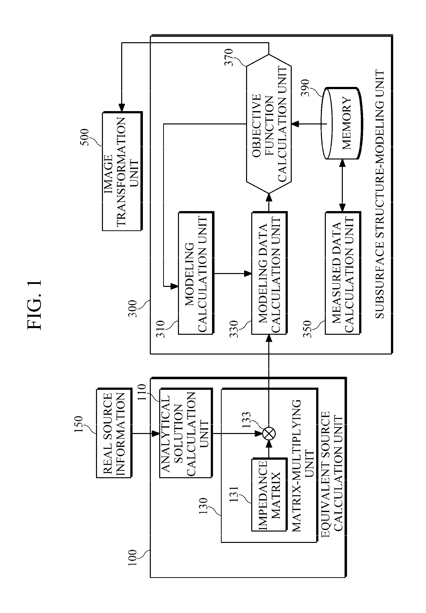
[0017]FIG. 1 is a diagram illustrating a configuration example of a subsurface structure imaging apparatus. As illustrated in FIG. 1, the subsurface structure imaging apparatus includes an equivalent source calculation unit 100 for obtaining an equivalent source that is equivalent to a real source and is at least one virtual source located at one of points defining an virtual grid of an area to be measured, and a subsurface modeling unit 300 for obtaining modeling parameter data about a subsurface structure, by performing Laplace-...


PUM


Abstract

The present invention relates to an imaging technique for modeling a subsurface structure through waveform inversion in the Laplace domain. According to the present invention, a source equivalent to the real source is calculated. The equivalent source is at least one source arranged on a virtual grid of the area to be measured, and the virtual grid has a large size which cannot be employed as the location of the real source in conventional techniques. The equivalent source has a vector obtained by multiplying an analytical solution vector and an impedance matrix of a Laplace domain wave equation, wherein said analytical solution vector is obtained from the analytical solution of a Laplace domain wave equation in a homogeneous half space by the real source.

Description

BACKGROUND[0001]1. Field[0002]The following description relates to subsurface structure imaging, and more particularly, to an imaging technique for modeling a subsurface structure through waveform inversion in the Laplace domain.[0003]2. Description of the Related Art[0004]to A technique for imaging a subsurface structure through wave equation modeling in the Laplace domain is disclosed in Korea Patent Application No. 10-2008-0025876 entitled “An apparatus for imaging a subsurface structure using waveform inversion in the Laplace domain and methods” thereof, which is a prior application filed by the present applicant. The technique calculates modeling parameters for a subsurface structure by performing Laplace-domain waveform inversion on seismic signals acquired by receivers arranged on an area to be measured. The modeling parameters are obtained through an iterative method. First, a subsurface structure model is estimated approximately using initial modeling parameters set, and th...

Claims


Application Information

Patent Timeline
IPC IPC(8): G01V1/38G01V1/28G06T17/05
CPCG01V2210/66G01V1/28
Inventor SHIN, CHANGSOO
Owner SHINS GEOPHYSICS
Learn More