
Motion vector detection apparatus for performing checker-pattern subsampling with respect to pixel arrays

a detection apparatus and motion vector technology, applied in the field of image compression, can solve the problems of heavy load on the versatile processor, loss in calculation speed and power consumption, etc., and achieve the effects of reducing production cost, reducing circuit scale, and increasing processing speed

Inactive Publication Date: 2005-04-28
SOCIONEXT INC
View PDF7 Cites 7 Cited by
  • Summary
  • Abstract
  • Description
  • Claims
  • Application Information

AI Technical Summary

Benefits of technology

The present invention provides a motion vector detection apparatus that can quickly and accurately detect motion vectors in videos. The apparatus uses a search history to avoid double searches and reduces processing speed and power consumption. It includes a first address generator, a first storage unit, a second address generator, a second storage unit, and a motion vector detector. The technical effects of the invention are improved motion vector detection speed and accuracy, reduced processing power consumption, and improved processing speed.

Problems solved by technology

Thereby, needless calculation is executed even though the position of this search area can be excluded from the candidates of search areas for motion vector detection, resulting in losses in calculation speed and power consumption.
However, even when an image of high resolution is not required especially, motion vector detection is carried out on the peripheral blocks, resulting in losses in calculation speed and power consumption.
In this case, however, a heavy load is put on the versatile processor.
In this case, however, if there is no change and therefore no search is required, operating the processor to obtain this result causes losses in calculation speed and power consumption.
Furthermore, when search for a reference block with respect to a target block is performed on reference blocks in the vicinity of the target block so as to minimize the sum of absolute differences in pixel values, there is a possibility that a once searched reference block may be searched again (double search), resulting in losses in calculation speed and power consumption.
Further, the sum of absolute differences is obtained by summing the absolute values of differences in pixel values between all pixels in a target block and all pixels in a reference block, even when an image of high resolution is not needed, calculation more than necessary is carried out, resulting in losses in calculation speed and power consumption.
In this case, however, since pixel data to be used for motion vector detection become part of read-in pixel data, pixel data other than those to be used for motion vector detection, which have already been read, are undesirably discarded, resulting in a loss in power consumption.
Even when data are transferred to this area, the data are not used for detection, resulting in a loss in power consumption.
Furthermore, since there is an overlap between reference areas corresponding to adjacent target blocks, reading pixel data in the entire reference area into the dedicated processor at every search on each target block causes losses in computation speed and power consumption.
In this case, motion vector detection cannot be carried out.
So, when the pixel data are read out in the horizontal direction, if the pixel values in positions between pixels in the vertical direction are desired, the processor should wait several cycles until the pixels required for interpolation in the vertical direction are prepared, resulting in a loss in the computation speed.

Method used


Image

  • Motion vector detection apparatus for performing checker-pattern subsampling with respect to pixel arrays
  • Motion vector detection apparatus for performing checker-pattern subsampling with respect to pixel arrays
  • Motion vector detection apparatus for performing checker-pattern subsampling with respect to pixel arrays

Examples


embodiment 1

[Embodiment 1]

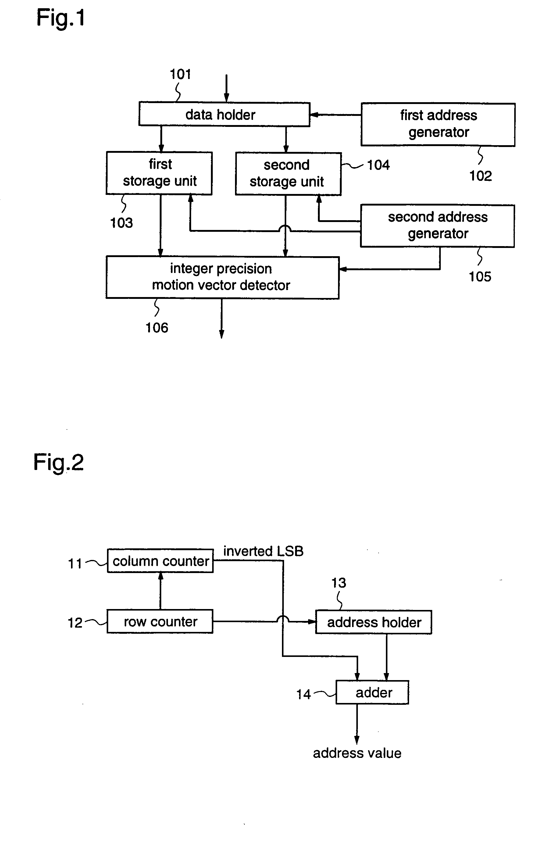
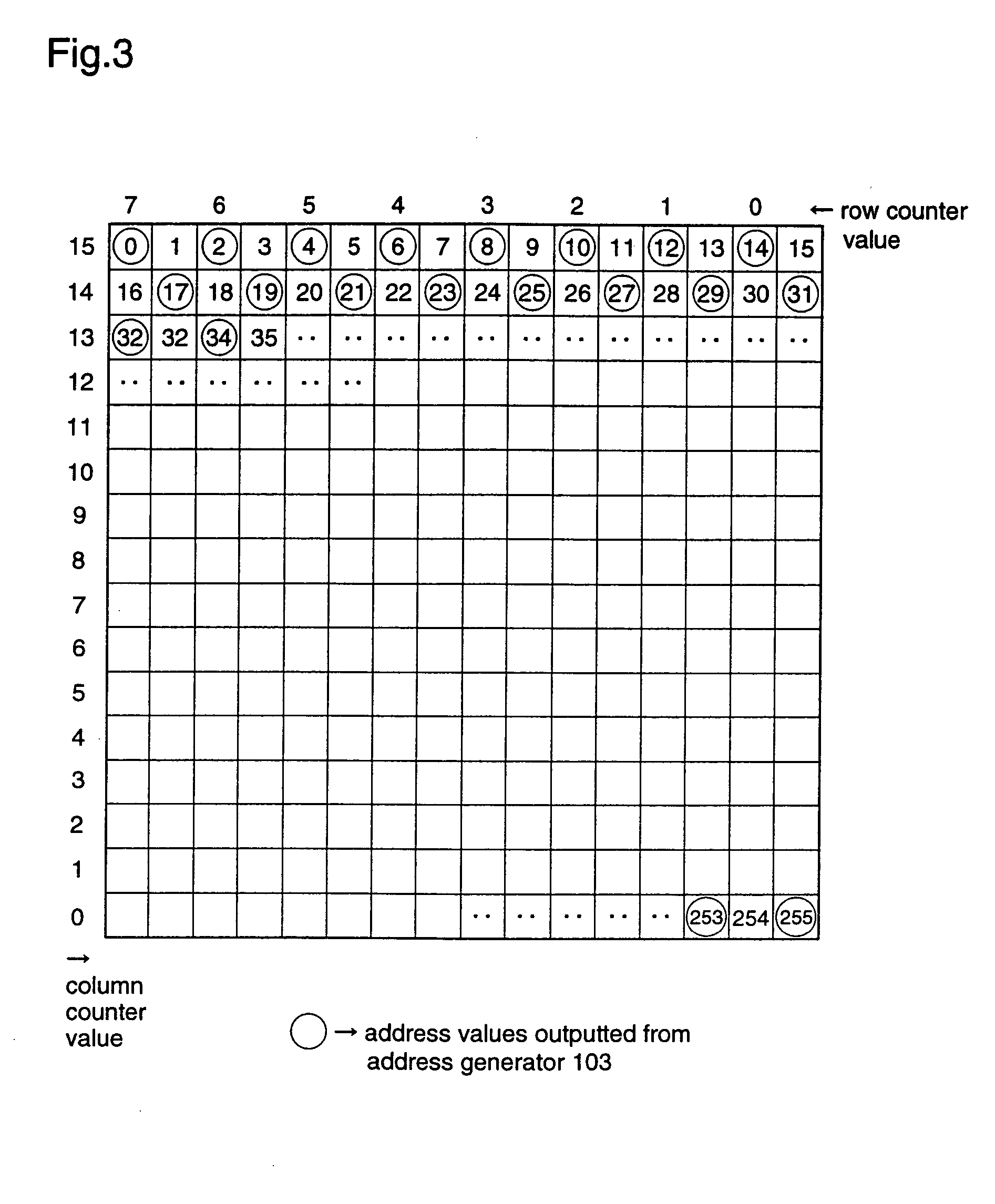
[0074] Hereinafter, a motion vector detection apparatus according to a first embodiment of the present invention will be described with reference to FIGS. 1 to 4.

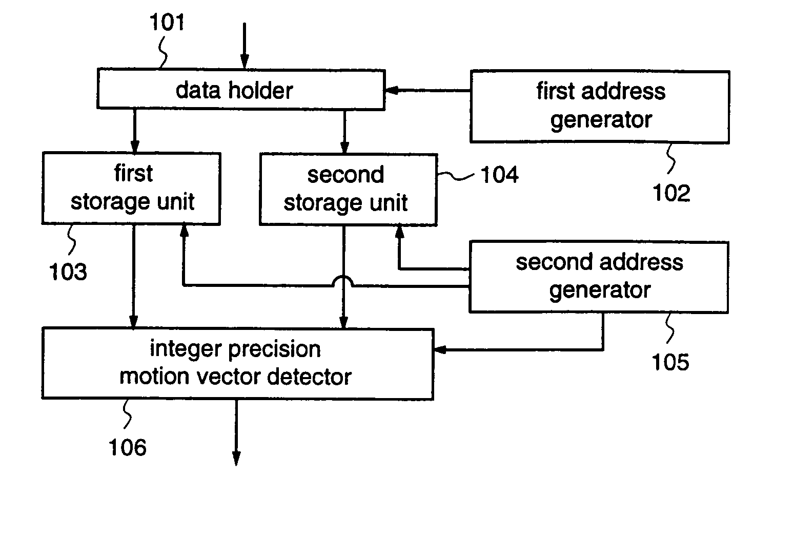
[0075]FIG. 1 is a block diagram illustrating the structure of a motion vector detection apparatus according to the first embodiment. In FIG. 1, the motion vector detection apparatus comprises a data holder 101, a first address generator 102, a first storage unit 103, a second storage unit 104, a second address generator 105, and an integer precision motion vector detector 106.

[0076] The data holder 101 is a bulk memory for holding image data. The data holder 101 outputs data of a reference area to the first storage unit 103, and outputs data of a target block to the second storage unit 104, according to an instruction from the first address generator 102.

[0077] The first address generator 102 generates, from the image data stored in the data holder 101, addresses of the data of the target block (data to be ...

embodiment 2

[Embodiment 2]

[0101] Hereinafter, a motion vector detection apparatus according to a second embodiment of the invention will be described with reference to FIGS. 5 to 7.

[0102]FIG. 5 is a block diagram illustrating the structure of a motion vector detection apparatus according to the second embodiment. With reference to FIG. 5, the motion vector detection apparatus is provided with a data holder 101, a first address generator 102, a first storage unit 103, a second storage unit 104, a second address generator 105, and an integer precision motion vector detector 206.

[0103] The motion vector detection apparatus of this second embodiment is different from the motion vector detection apparatus of the first embodiment only in that the integer precision motion vector detector 206 is featured. Therefore, the same constituents as those of the motion vector detection apparatus according to the first embodiment are given the same reference numerals, and description of these constituents will...

embodiment 3

[Embodiment 3]

[0134] Hereinafter, a motion vector detection apparatus according to a third embodiment of the present invention will be described with reference to FIGS. 8 to 10.

[0135]FIG. 8 is a block diagram illustrating the structure of a motion vector detection apparatus according to the third embodiment. With reference to FIG. 8, the motion vector detection apparatus comprises a data holder 101, a first address generator 102, a first storage unit 103, a second storage unit 104, a second address generator 105, an integer precision motion vector detector 206, and a search history holder 301.

[0136] The motion vector detection apparatus according to this third embodiment is different from the motion vector detection apparatus of the second embodiment only in that the histories of reference blocks on which search has been done are stored to avoid double search on the same reference block. Therefore, the same constituents of the motion vector detection apparatus as those already des...


PUM


Abstract

A motion vector detection apparatus for detecting a motion vector by performing block matching between a target block including a plurality of pixels in a current image, and a reference block including a plurality of pixels in a predetermined reference area in a past image that is previous to the current image, the apparatus including a first address generator for generating addresses of data in the target block and addresses of data in the reference area; a first storage unit for holding data of the reference area designated by the first address generator; a second storage unit for holding data of the target block designated by the first address generator; a second address generator for generating addresses of data to be outputted from the first storage unit and the second storage unit; and a motion vector detector for detecting a motion vector by using the data outputted from the first storage unit and the data outputted from the second storage unit; wherein the motion vector detector subtracts the absolute values of differences in pixel data between the reference block and the target block, one by one, from a threshold value, and when the result of subtraction becomes negative, the motion vector detector stops calculation of the sum of absolute differences in the corresponding position.

Description

FIELD OF THE INVENTION [0001] The present invention relates to image compression and, more particularly, to motion vector detection applicable to H.261, H263, MPEG4, and the like, which are the standards for low bit rate, aimed at image communication. BACKGROUND OF THE INVENTION [0002] In the existing standards for low bit rate aimed at image communication, such as H.261, H263, MPEG4, etc., motion vector detection is carried out for data compression using correlation between frames. [0003] This motion vector detection is usually performed on a block (target block) comprising plural pixels in a current image (frame), and block matching is performed to check where the target block is positioned in a past image (frame) that is previous to the current image, thereby detecting a motion vector indicating the direction and amount of the motion of image. [0004]FIG. 31 is a diagram for explaining the conventional motion vector detection. With reference to FIG. 31, a target block T is a block...

Claims


Application Information

Patent Timeline
Patent Type & Authority Applications(United States)
IPC IPC(8): H03M7/36H04N5/14H04N19/00H04N19/105H04N19/136H04N19/182H04N19/196H04N19/42H04N19/423H04N19/51H04N19/513H04N19/527H04N19/56H04N19/57
CPCH04N5/145H04N19/53H04N19/433H04N19/51
Inventor ARITA, MIKIKUROHMARU, SHUNICHI
Owner SOCIONEXT INC
Learn More