Corrected ball diameter calculating method and form measuring instrument

a technology of calculating method and form measuring instrument, which is applied in the direction of instruments, mechanical measurement arrangements, mechanical roughness/irregularity measurements, etc., can solve problems such as workpiece rotation, error arising in analysis, and affect the effect of error

Active Publication Date: 2010-09-30
MITUTOYO CORP
View PDF9 Cites 20 Cited by
  • Summary
  • Abstract
  • Description
  • Claims
  • Application Information

AI Technical Summary

Benefits of technology

[0051]According to the present invention, average values of the corrected ball diameters that have been calculated per each of the height positions are calculated as the analysis-use corrected ball diameters, so the amount of calculation that the form measuring instrument processes can be reduced in comparison to a configuration that calculates the analysis-use corrected ball diameters from predetermined approximate functions per each of the height positions of the workpiece that are measured.

Problems solved by technology

However, it has been found that when a rotary table is used in this manner to measure an workpiece and the corrected ball diameters are used to analyze the profile and the like of the workpiece, error ends up arising in the analysis result even though the error is slight.
Moreover, it has been found that this error is affected by the height position of the workpiece that is measured.
It is thought that when an workpiece is measured while the workpiece is caused to rotate, error resulting from measuring the workpiece while causing the workpiece to rotate and error corresponding to the height position that is measured arises because of runout of the rotary table, whirl of the workpiece and flexure of the stylus or the like, and error ends up arising in the analysis result because of these measurement errors.
That is, it is thought that because error that arises by measuring an workpiece while causing the workpiece to rotate and error that arises depending on the height position that is measured are not included in the conventional corrected ball diameters that are calculated by measuring the master ball M in a stationary state, when the conventional corrected ball diameters are used to analyze the profile and the like of the workpiece when the workpiece has been measured while the workpiece has been caused to rotate, analysis precision ends up dropping in correspondence to these errors not being included in the corrected ball diameters.

Method used


Image

  • Corrected ball diameter calculating method and form measuring instrument
  • Corrected ball diameter calculating method and form measuring instrument
  • Corrected ball diameter calculating method and form measuring instrument

Examples


first embodiment

1. Overall Configuration of Coordinate Measuring Machine

[0067]A first embodiment of the present invention will be described below on the basis of the drawings. Hereinafter, the same reference numerals will be given to the same functional portions as those of the conventional coordinate measuring machine 1 described in the “Related Art” section, and description of those same functional portions will be omitted or simplified.

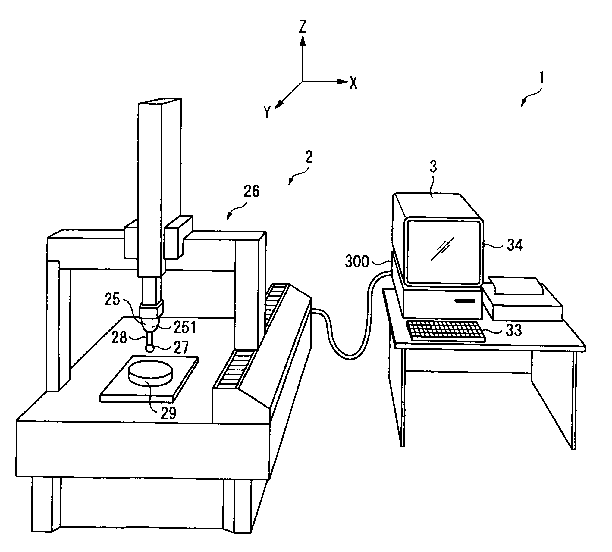
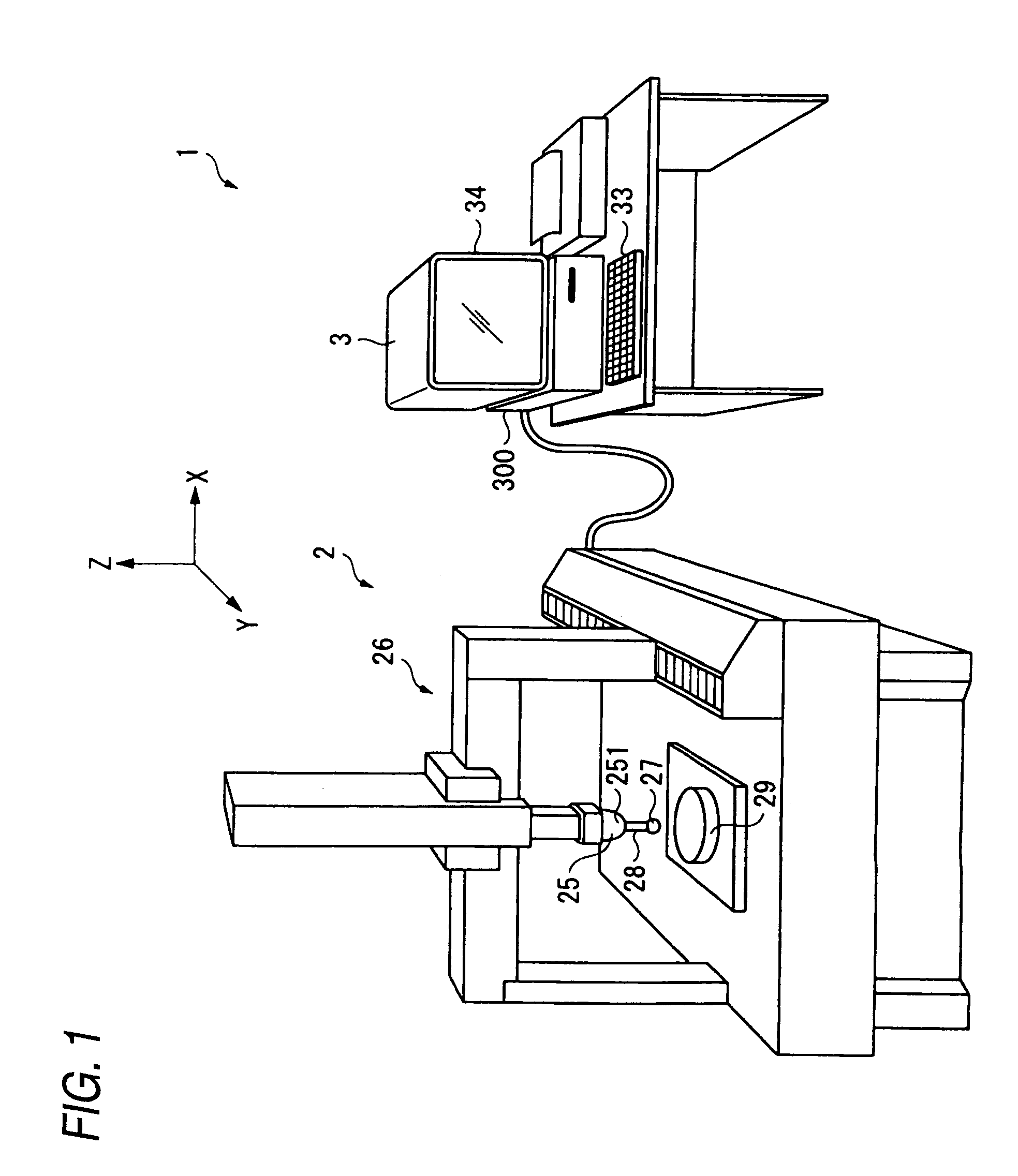
[0068]FIG. 1 is a perspective diagram showing a coordinate measuring machine 1 that serves as a form measuring instrument pertaining to the present embodiment.

[0069]The coordinate measuring machine 1 is equipped with a measuring machine body 2 and a PC 3.

2. Overall Configuration of Measuring Machine Body

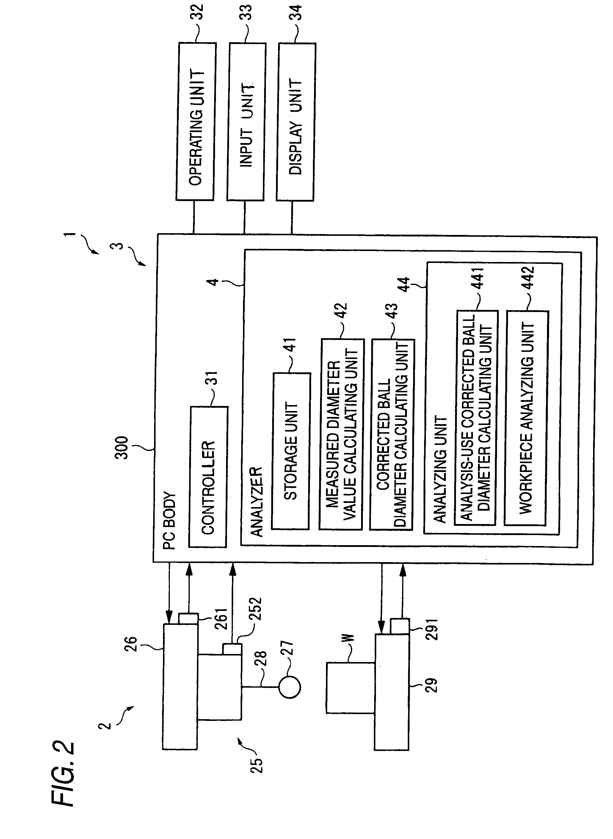
[0070]The measuring machine body 2 is equipped with: a rotary table 29 that is capable of rotating an workpiece that is placed thereon; a rotation angle sensor 291 (see FIG. 2) that detects the rotation angle of the rotary table 29; a probe 25 that has a stylus 28 ...

second embodiment

[0123]The present embodiment is characterized in that the analysis-use corrected ball diameter calculating unit calculates, as the analysis-use corrected ball diameters, average values of the corrected ball diameters that have been calculated per each of the height positions by the corrected ball diameter calculating unit. The other configurations of the present embodiment are the same as those of the first embodiment. In this embodiment also, the same effects (1) to (3) as the first embodiment can be achieved, and the following effect can also be achieved.

[0124](5) The analysis-use corrected ball diameter calculating unit calculates, as the analysis-use corrected ball diameters, average values of the corrected ball diameters that have been calculated per each of the height positions, so the amount of calculation that the form measuring instrument performs can be reduced in comparison to the first embodiment that calculates the analysis-use corrected ball diameters from predetermine...


PUM


Abstract

A corrected ball diameter calculating method includes: preparing a reference gauge that has at least one reference peripheral surface of an outer peripheral surface and an inner peripheral surface; valuing of diameter values of the reference peripheral surface at a plurality of different height positions from a bottom surface of the reference gauge; calculating calibrated diameter values per each of the height positions; placing the reference gauge on the rotary table and causing the stylus tip to touch a plurality of measurement sites on the reference peripheral surface at each of the height positions to calculate measured diameter values that are diameter values of a circle passing through the neighborhood of center points of the stylus tip; and calculating the corrected ball diameters per each of the height positions from the calibrated diameter values and the measured diameter values that are calculated per each of the height positions.

Description

CROSS-REFERENCE TO RELATED APPLICATIONS[0001]This application is based upon and claims the benefit of priority from Japanese Patent Application No. 2009-073572, filed Mar. 25, 2009, the entire contents of which are incorporated herein by reference.BACKGROUND[0002]1. Field of the Invention[0003]The present invention relates to a corrected ball diameter calculating method and a form measuring instrument.[0004]2. Description of the Related Art[0005]Conventionally, as form measuring instruments that measure the dimensions and the profile of an workpiece, there have been known coordinate measuring machines, for example.[0006]FIG. 10 is a diagram showing a conventional coordinate measuring machine 1.[0007]The coordinate measuring machine 1 is equipped with a measuring machine body 2 and a personal computer (PC) 3 that processes measurement data acquired by the measuring machine body 2 to determine the dimensions and the profile of an workpiece W.[0008]The measuring machine body 2 is equip...

Claims


Application Information

Patent Timeline
Patent Type & Authority Applications(United States)
IPC IPC(8): G01B1/00G06F19/00G01B5/00G01B5/08
CPCG01B5/008G01B5/20G01B21/045G01B5/28G01B21/042G01B5/201
Inventor NODA, TAKASHIDEGUCHI, HIROMI
Owner MITUTOYO CORP
Why Eureka
Try Eureka