Method and Apparatus for Detecting RF Field Strength
- Summary
- Abstract
- Description
- Claims
- Application Information
AI Technical Summary
Benefits of technology
Problems solved by technology
Method used
Image
Examples
Embodiment Construction
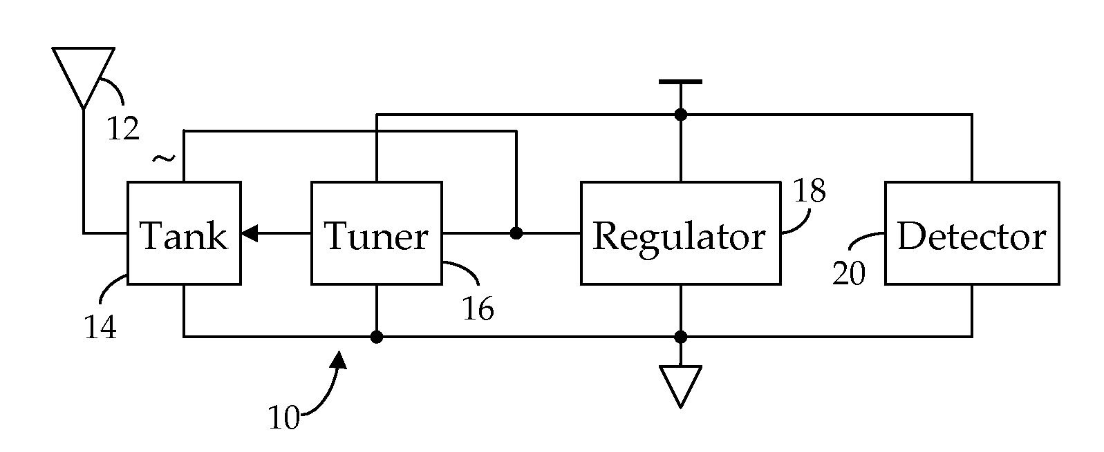
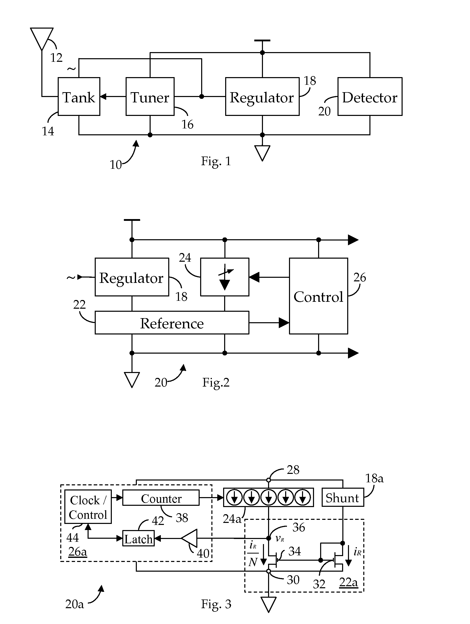
[0030]Shown in FIG. 1 is an RF receiver circuit 10 suitable for use in an RFID application. As I have described in my Related References, an RF signal electromagnetically coupled to an antenna 12 is received via a tank circuit 14, the response frequency, fR, of which is dynamically varied by a tuner 16 to better match the transmission frequency, fC, of the received RF signal, thus obtaining a maximum power transfer. In particular, as further noted in the Related Applications, the RMS voltage induced across the tank circuit 14 by the received RF signal is quantized by tuner 16 and the developed quantization employed to control the impedance of the tank circuit 14. As also described in the Related References, the unregulated, AC current induced in the tank circuit 14 by the received RF signal is conditioned by a regulator 18 to provide regulated DC operating power to the receiver circuit 10. In accordance with my present invention, I now provide a field strength detector 20, also know...
PUM
 Abstract
Description
Claims
Application Information
 - R&D
- Intellectual Property
- Life Sciences
- Materials
- Tech Scout
- Unparalleled Data Quality
- Higher Quality Content
- 60% Fewer Hallucinations
Browse by: Latest US Patents, China's latest patents, Technical Efficacy Thesaurus, Application Domain, Technology Topic, Popular Technical Reports.
© 2025 PatSnap. All rights reserved.Legal|Privacy policy|Modern Slavery Act Transparency Statement|Sitemap|About US| Contact US: help@patsnap.com


