Spinal Stabilization Device

a spinal column and stabilization device technology, applied in the field of spinal column stabilization devices, can solve the problems of unfavorable stability, unfavorable stability, unfavorable stability, etc., and achieve the desired level of flexibility and stability, improve construction and design, and reduce operation time

Active Publication Date: 2011-12-08
DEPUY SYNTHES PROD INC
View PDF0 Cites 14 Cited by
  • Summary
  • Abstract
  • Description
  • Claims
  • Application Information

AI Technical Summary

Benefits of technology

[0020]To overcome the deficiencies of conventional spinal fixation devices, in one embodiment, the inventor of the present invention has invented a novel flexible spinal fixation device with an improved construction and design that is durable and provides a desired level of flexibility and stability.
[0021]As a result of long-term studies to reduce the operation time required for minimally invasive spinal surgery, to minimize injury to tissues near the surgical area, in another embodiment, the invention provides a method and device for accurately and quickly finding a position of the spinal column in which securing members of the spinal fixation device will be inserted. A novel guidance / marking device is used to indicate the position in the spinal column where the securing members will be inserted.

Problems solved by technology

Although the concept of the wire guidance system is a good one, in practice, the guide wire has been very difficult to use.
Because it is a relatively long and thin wire, the structural integrity of the guide wire often fails during attempts to drive one end of the wire into the pedicle bone, making the process unnecessarily time-consuming and laborious.
Furthermore, because the wire bends and crimps during insertion, it does not provide a smooth and secure anchor for guiding subsequent tooling and pedicle screws to the entry point on the pedicle.
Thus, current wire guidance systems pose a potential risk of misplacement or pedicle breakage.
Finally, because one end of the wire remains protruding out of the head of the pedicle screw, and the patient's back, this wire hinders freedom of motion by the surgeon in performing the various subsequent procedures involved in spinal fixation surgery.
Most conventional spinal fixation devices are too rigid and inflexible.
This excessive rigidity causes further abnormalities and diseases of the spine, as well as significant discomfort to the patient.
Although some existing spinal fixation devices do provide some level of flexibility, these devices are not designed or manufactured so that varying levels of flexibility may be easily obtained to provide a desired level of flexibility for each particular patient.
Additionally, prior art devices having flexible connection units (e.g., rods or plates) pose a greater risk of mechanical failure and do not provide long-term durability and stabilization of the spine.
Furthermore, existing methods of performing the spinal fixation procedure are unnecessarily traumatic to the patient due to the difficulty in finding the precise location of the spinal pedicle or sacral of the backbone where the spinal fixation device will be secured.

Method used


Image

  • Spinal Stabilization Device
  • Spinal Stabilization Device
  • Spinal Stabilization Device

Examples


Embodiment Construction

[0106]The invention is described in detail below with reference to the figures wherein like elements are referenced with like numerals throughout.

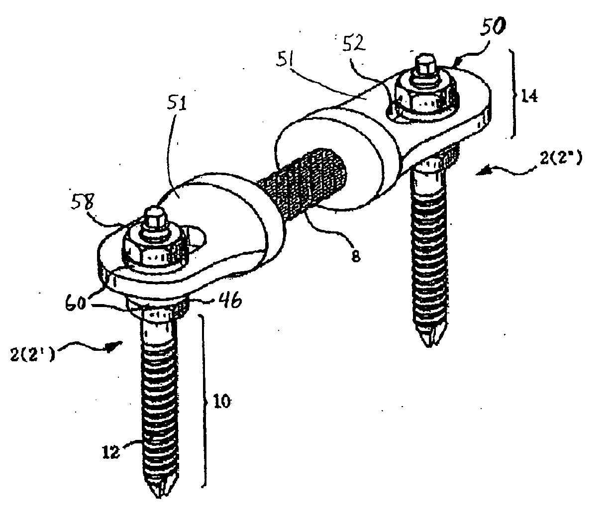
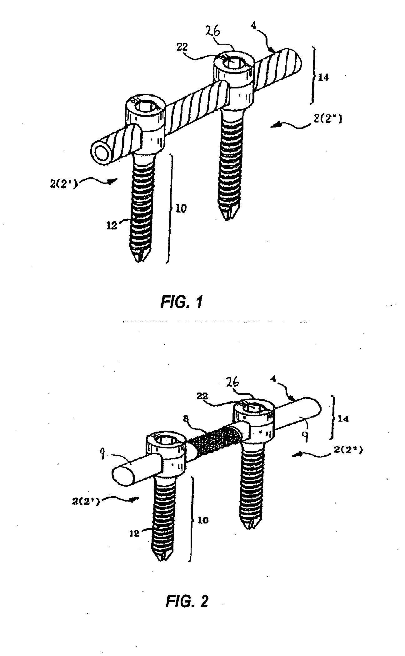
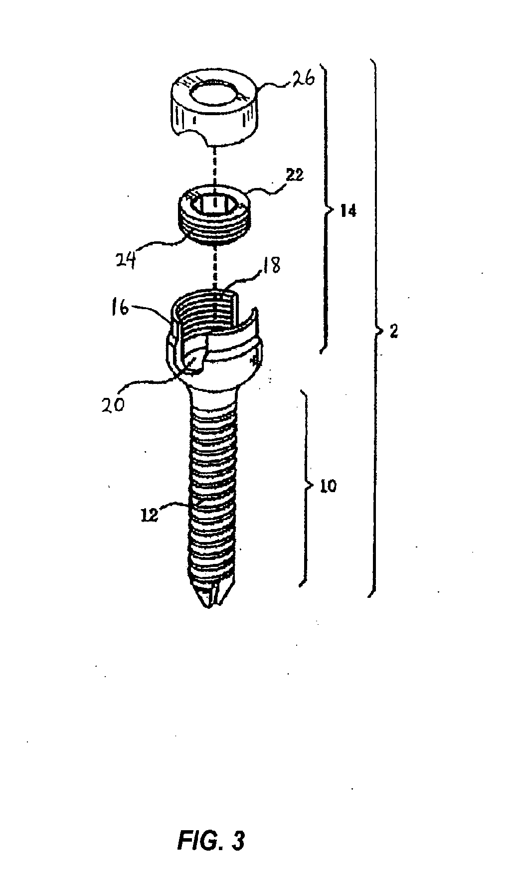
[0107]FIG. 1 depicts a spinal fixation device in accordance with one embodiment of the present invention. The spinal fixation device includes two securing members 2 (designated as 2′ and 2″), and a flexible fixation rod 4 configured to be received and secured within a coupling assembly 14, as described in further detail below with respect to FIG. 3. Each securing member 2 includes a threaded screw-type shaft 10 configured to be inserted and screwed into a patient's spinal pedicle. As shown in FIG. 1, the screw-type shaft 10 includes an external spiral screw thread 12 formed over the length of the shaft 10 and a conical tip at the end of the shaft 10 configured to be inserted into the patient's spinal column at a designated location. Other known forms of the securing member 2 may be used in connection with the present invention provided the...


PUM


Abstract

A flexible connection unit for use in a spinal fixation device that includes: a longitudinal member having first and second ends and a flexible member interposed between the first and second ends, at least one of the first end and second end configured to be engaged by a first bone securing member; and at least one spacer located between the first and second ends, the spacer comprising a resilient element and a ring element encircling at least a portion of the resilient element, wherein the ring element is configured to be engaged by a second bone securing member.

Description

CROSS REFERENCE TO RELATED APPLICATIONS[0001]This application is a continuation of U.S. patent application Ser. No. 11 / 705,953, filed Feb. 13, 2007, which is continuation-in-part of U.S. patent application Ser. No. 11 / 072,886, filed Mar. 3, 2005, which is a continuation-in-part of U.S. patent application Ser. No. 11 / 009,097, filed Dec. 10, 2004, which is continuation-in-part of U.S. patent application Ser. No. 10 / 798,014, filed Mar. 10, 2004, which is a continuation-in-part of U.S. patent application Ser. No. 10 / 728,566, filed on Dec. 5, 2003, which claims the benefit of priority under 35 U.S.C. §119(a) to Korean Application Serial No. 2003-0066108, filed on Sep. 24, 2003, the entireties of which are incorporated by reference herein.BACKGROUND[0002]1. Field of the Invention[0003]The present invention relates to a method and system for stabilizing a spinal column and, more particularly, to a method and system of spinal fixation in which one or more screw type securing members are imp...

Claims


Application Information

Patent Timeline
Patent Type & Authority Applications(United States)
IPC IPC(8): A61B17/70A61BA61B17/00A61B17/17A61B17/34A61B17/56A61B17/58A61B17/60A61B19/00A61F2/00A61F2/30A61F2/32A61F2/34A61F2/36A61F2/38A61F5/00A61F11/00
CPCA61B17/02A61B17/88A61B17/3421A61B17/3423A61B17/3439A61B17/3468A61B17/3472A61B17/7004A61B17/7007A61B17/701A61B17/7032A61B17/8897A61B19/54A61B2017/00004A61B2017/00862A61B2017/0256A61B2019/5287A61B2019/5416A61B2019/5487A61B17/1757A61B2090/363A61B2090/3916A61B90/39A61B2090/3987
Inventor JAHNG, TAE-AHN
Owner DEPUY SYNTHES PROD INC
Why Eureka
Try Eureka