Electrochemical cell interconnect

Inactive Publication Date: 2005-02-15
VERSA POWER SYST
View PDF25 Cites 22 Cited by
  • Summary
  • Abstract
  • Description
  • Claims
  • Application Information

AI Technical Summary

Benefits of technology

The present invention includes an interconnect plate having improved construction and design which simplifies the manufacturing of the plate and provides gre

Problems solved by technology

Solid oxide fuel cells typically operate at high temperature, often in excess of 600° C. This limits the selection of materials available for use as an interconnect that are able to withstand this temperature, and to simultaneously withstand an oxidizing environment on one side of the interconnect, and a partial reducing environment on the other.
Most prior art interconnects have used ceramic materials and composites, however these materials demonstrate inferior electrical conductivity as compared to metals, and typically are not successful in withstanding both oxidizing and reducing environments simultaneously.
Ceramic materials also are expensive to purchase as raw materials, require moulding or other processing, and then firing or sintering.
These steps are all labour intensive and require significant amounts of time to process.
In addition, fine tolerances that are required

Method used


Image

  • Electrochemical cell interconnect
  • Electrochemical cell interconnect
  • Electrochemical cell interconnect

Examples


Embodiment Construction

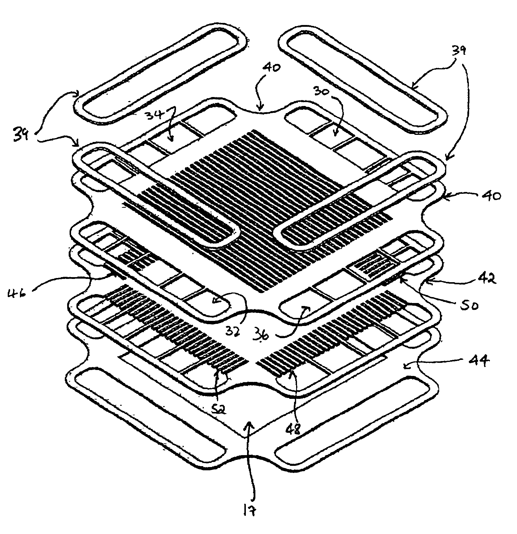
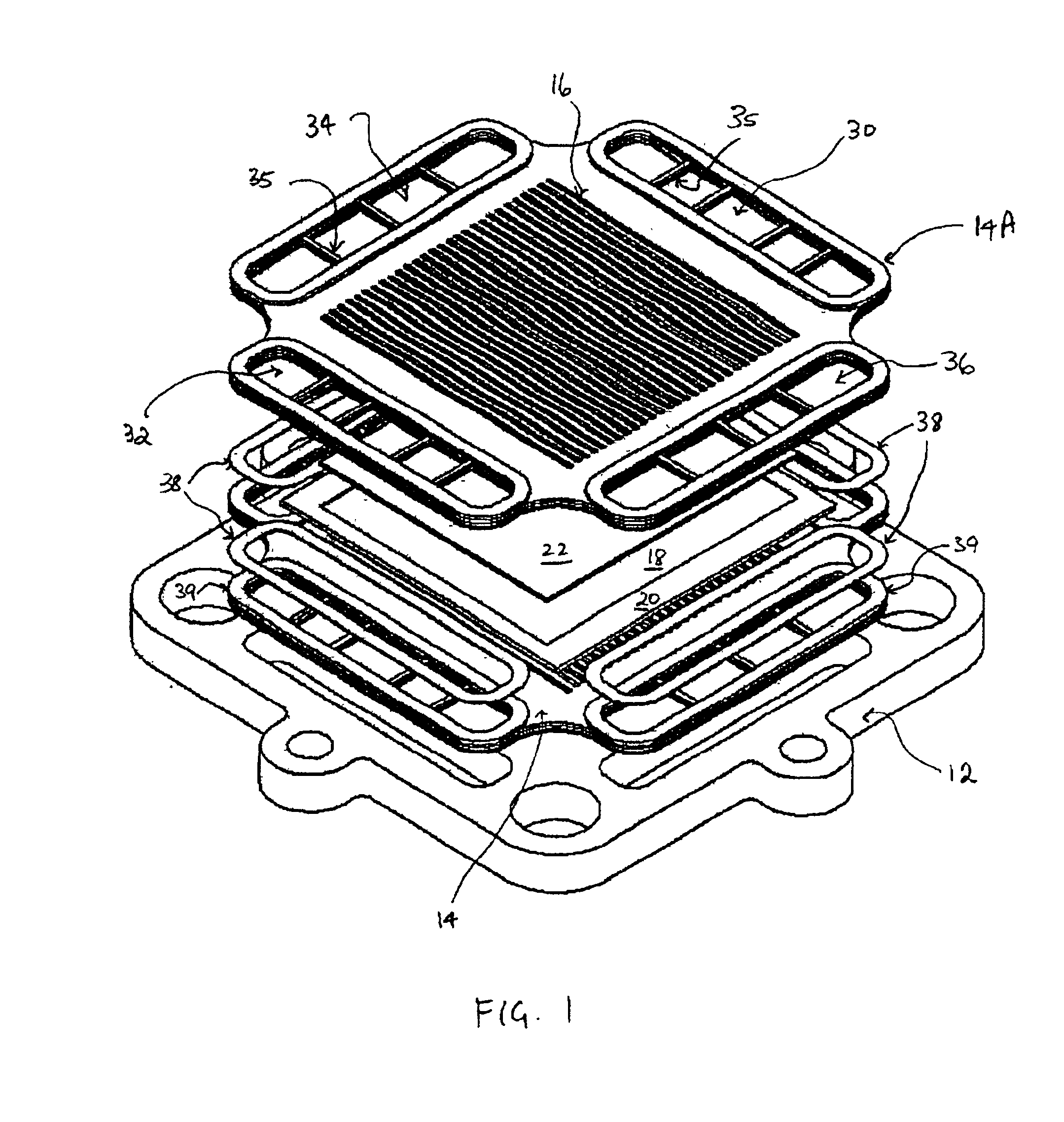
As shown in FIG. 1, a fuel cell stack (10) is comprised of several components. As used herein, a “membrane unit” consists of a ceramic membrane having an electrolyte layer and opposing anode and cathode layers. A “fuel cell unit” consists of a membrane unit, an interconnect plate and the associated seals and other elements. A fuel cell stack is comprised of a plurality of repeated fuel cell units.

The base plate (12) serves as a fixture for the stack, and provides structural support for the units that comprise the stack. The bottom interconnect plate (14) has cut into one of its surface a plurality of gas flow fields (16) that serve as conduits for moving either fuel gas or oxidant gases such that they may contact the adjacent ceramic membrane unit (18) membrane. A fuel cell membrane unit (18) operates such that one side of the cell membrane unit (18) is in contact with the fuel gas, and the other side of the cell membrane unit (18) is in contact with oxidant gasses. The membrane uni...


PUM


Abstract

A solid oxide fuel cell stack incorporates metallic interconnects each of which includes a fuel intake manifold, a fuel exhaust manifold, an oxidant intake manifold and an oxidant exhaust manifold. The fuel side of the interconnect defines a fuel flow field surrounded by a continuous sealing surface and in fluid communication with the fuel intake and exhaust manifold. The oxidant side of the interconnect defines an oxidant flow field surrounded by a continuous sealing surface and in fluid communication with the oxidant intake and exhaust manifolds. The interconnect may be fabricated by brazing together three stainless steel plates having overlapping openings to permit the exclusionary flow of fuel and oxidant through the interconnect.

Description

BACKGROUND OF INVENTIONThe present invention relates to a solid electrolyte fuel cell configuration comprising metallic interconnect elements to act as fuel and oxidant manifolds and distribution channels.In a fuel cell, oxidant and fuel are electrochemically reacted without burning to produce electricity directly. The reactants are supplied to the cell through manifolds and flow fields that direct reactants to the appropriate sides of a solid ceramic membrane, that membrane that acts as an electrolyte. The membrane is coated with electrodes on both sides, and is impervious to the transfer of electrons, but not ions of the oxidant. Thus the streams of reactants are kept separate, but the electrons and ions from the reactants are allowed contact to effect the reaction. During operation electrons are emitted at the fuel side electrode of the solid electrolyte membrane whereas electrons are absorbed at the oxygen side electrode thereby generating a potential difference between the two ...

Claims


Application Information

Patent Timeline
IPC IPC(8): H01M8/02H01M8/24H01M8/12
CPCH01M8/0206H01M8/021H01M8/0228H01M8/0258H01M8/2425H01M8/0247Y02E60/50H01M8/2432H01M8/2483H01M8/0276H01M8/241
Inventor GHOSH, DEBABRATAPASTULA, MICHAELPREDIGER, DENNISPERRY, MARTINHORVATH, ARPADLUMSDEN, JIM
Owner VERSA POWER SYST
Why Eureka
Try Eureka