Storage apparatus and control method therefor

a storage apparatus and control method technology, applied in the field of storage apparatus and control method therefor, can solve the problems of error-correction-dedicated storage medium bottleneck in operation, and cannot be applied to raid mode other than raid mod

Inactive Publication Date: 2011-12-08
BUFFALO CORP LTD
View PDF13 Cites 202 Cited by
  • Summary
  • Abstract
  • Description
  • Claims
  • Application Information

AI Technical Summary

Benefits of technology

[0019]According to the above-mentioned feature, it is possible to provide a storage apparatus that can operate in RAID modes other than RAID 3 or RAID 4 and can change from one RAID mode to another while maintaining the contents stored in the pre-existing storage media.
[0020]According to another feature of a storage apparatus of this invention, before the addition of the new storage medium, the controller causes the pre-existing stor...

Problems solved by technology

Firstly, with the technique disclosed in Patent Literature 1, the RAID mode stays in RAID 3 or 4 even after the new storage medium has been added and cannot be changed to another RAID mode.
Secondly, the technique disclosed in Patent Literature 1 requires the provision of an error-correction-...

Method used


Image

  • Storage apparatus and control method therefor
  • Storage apparatus and control method therefor
  • Storage apparatus and control method therefor

Examples


first embodiment

(1) First Embodiment

[0036]In the first embodiment, (1.1) Overall Configuration, (1.2) Detailed Configuration of RAID-Functioning NAS, (1.3) RAID Mode Change from RAID 5 to RAID 6, and (1.4) Obtained Results, are described in this order.

(1.1) Overall Configuration

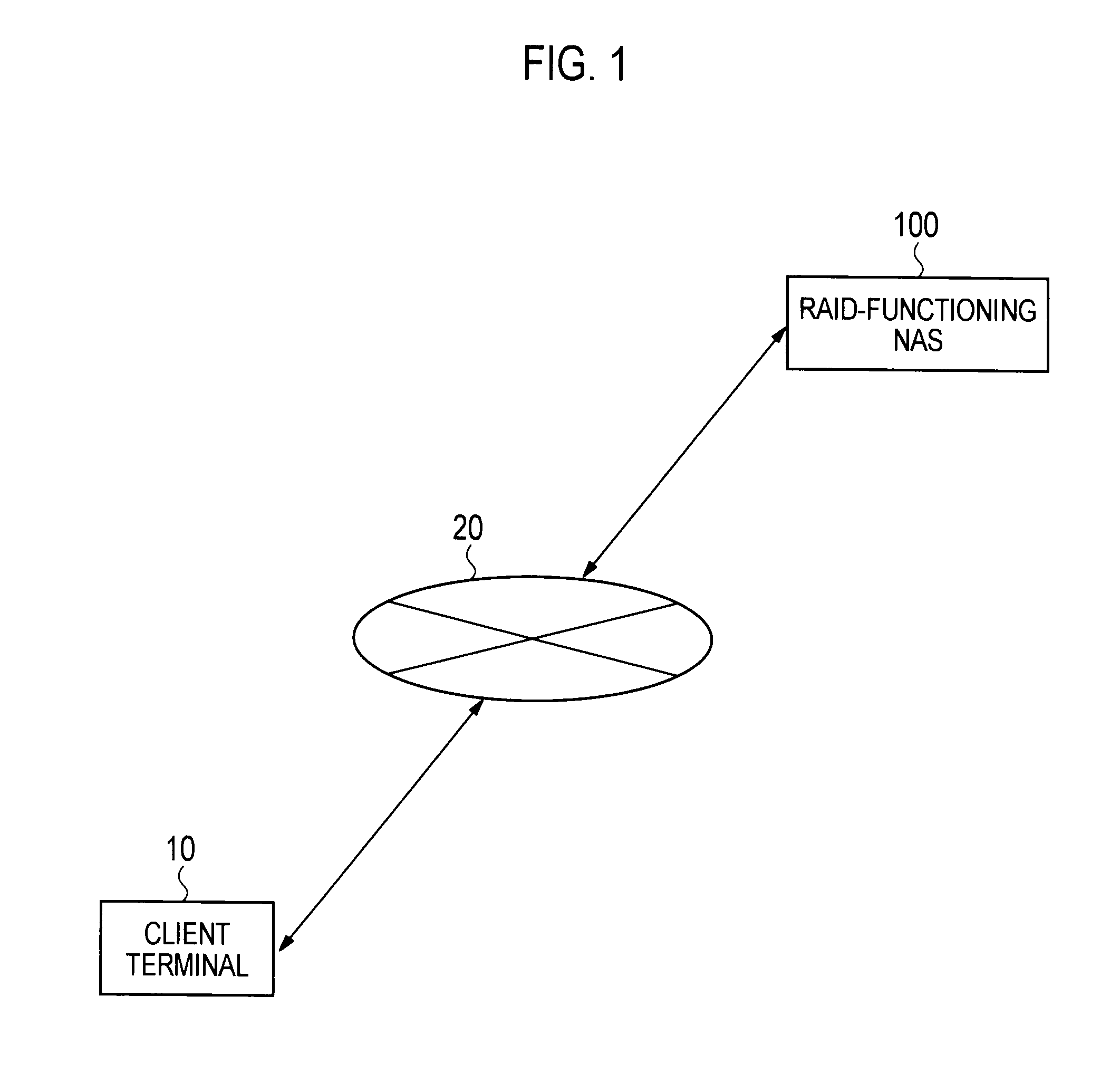
[0037]FIG. 1 shows in block diagram a communication system including a RAID-functioning NAS 100 according to this embodiment.

[0038]As shown in FIG. 1, the RAID-functioning NAS 100 is connected to a network 20 such as a local area network (LAN).

[0039]A client terminal 10 is a personal computer (PC), a network-connectable television set, or the like. The client terminal 10 is connected to the network 20 and performs data communications with the RAID-functioning NAS 100 through the network 20.

[0040]The RAID-functioning NAS 100 stores the data received from the client terminal 10 through the network 20.

[0041]The RAID-functioning NAS 100 according to the first embodiment functions as RAID 5 and RAID 6. In RAID 5, error correction...

second embodiment

(2) Second Embodiment

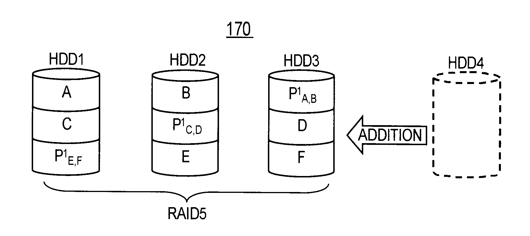
[0080]RAID mode change from RAID 1 to RAID 5 is described in a second embodiment.

[0081]Description of the second embodiment is given below in the order of (2.1) Detailed Configuration of RAID-Functioning NAS, (2.2) RAID Mode Change from RAID 1 to RAID 5, and (2.3) Obtained Result. The description is mainly given on what is different from the first embodiment and no overlapping explanation will be given.

(2.1) Detailed Configuration of RAID-Functioning NAS

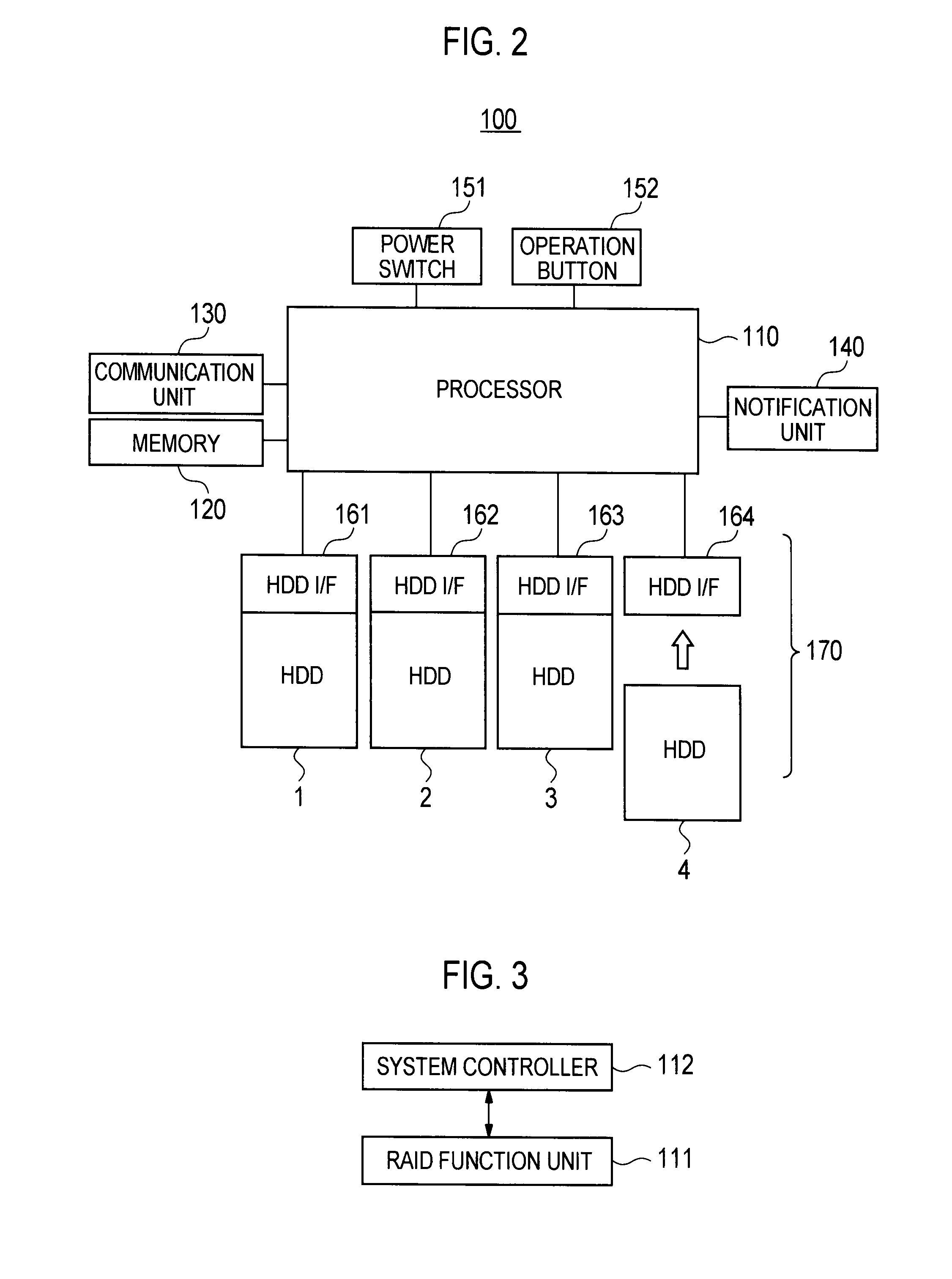
[0082]FIG. 6 shows a configuration of hardware of the RAID-functioning NAS 100 according to the second embodiment.

[0083]As shown in FIG. 6, the RAID-functioning NAS 100 according to the second embodiment to which at most three HDDs can be attached, includes HDD I / Fs 161 to 163. The RAID-functioning NAS 100 may be configured to include four or more HDDs attached thereto.

[0084]The RAID-functioning NAS 100 according to the second embodiment can work as at least RAID 1 or RAID 5. In RAID 1, the same data is stored in...


PUM


Abstract

A storage apparatus includes a storage unit including plural storage media, and a controller for controlling the storage unit. After a new storage medium has been added to the storage unit, the controller causes the new storage medium to store error correction codes for data stored in the respective storage media pre-existing in the storage unit. When new data is stored in the storage unit after the addition of the new storage medium, the controller causes the pre-existing storage media and the new storage medium to dispersedly store the new data and error correction codes for the new data.

Description

CROSS REFERENCE TO RELATED APPLICATION[0001]This application is based upon and claims the benefit of priority from the prior Japanese Patent Application No. 2010-128327 filed on Jun. 3, 2010; the entire contents of which are incorporated herein by reference.BACKGROUND OF THE INVENTION[0002]1. Field of the Invention[0003]This invention relates to a storage apparatus to which the idea of a RAID system is applied and to a control method for the storage apparatus.[0004]2. Description of the Related Art[0005]Redundant arrays of inexpensive disks (RAID) are a widely used technology capable of building a highly reliable storage apparatus by the use of plural storage media such as hard disk drives (HDDs). In the RAID technology, plural storage media in combination work as a single logical storage unit (i.e. disk array).[0006]Redundancy and data arrangement in RAID (hereinafter referred to as “RAID mode”) are determined mainly depending on the number of the storage media. RAID 1 uses two or ...

Claims


Application Information

Patent Timeline
IPC IPC(8): G06F12/16
CPCG06F11/1096G06F2211/1061G06F2211/1004G06F3/0607G06F3/0632G06F3/0689
Inventor GOTO, SATORUHARA, YUKIHITO
Owner BUFFALO CORP LTD
Why Eureka
Try Eureka