Push mount wall panel

Inactive Publication Date: 2011-12-15
OWENS CORNING INTELLECTUAL CAPITAL LLC
View PDF11 Cites 23 Cited by
  • Summary
  • Abstract
  • Description
  • Claims
  • Application Information

AI Technical Summary

Benefits of technology

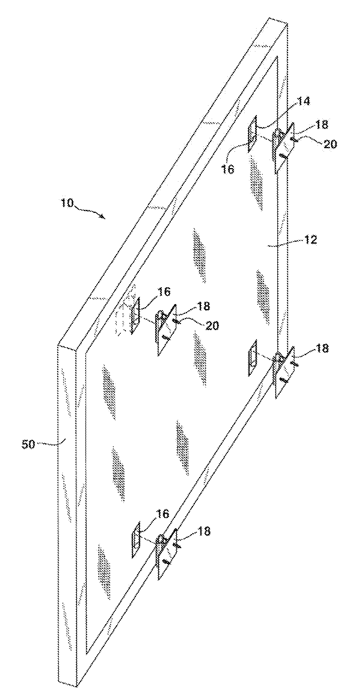
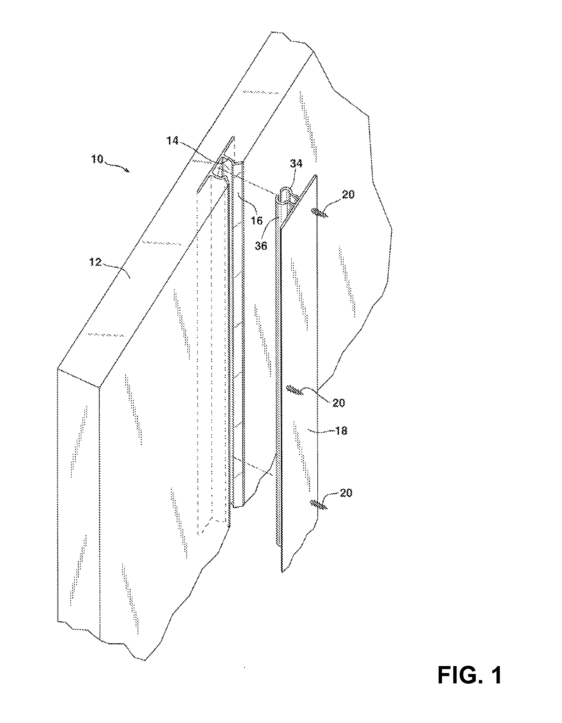
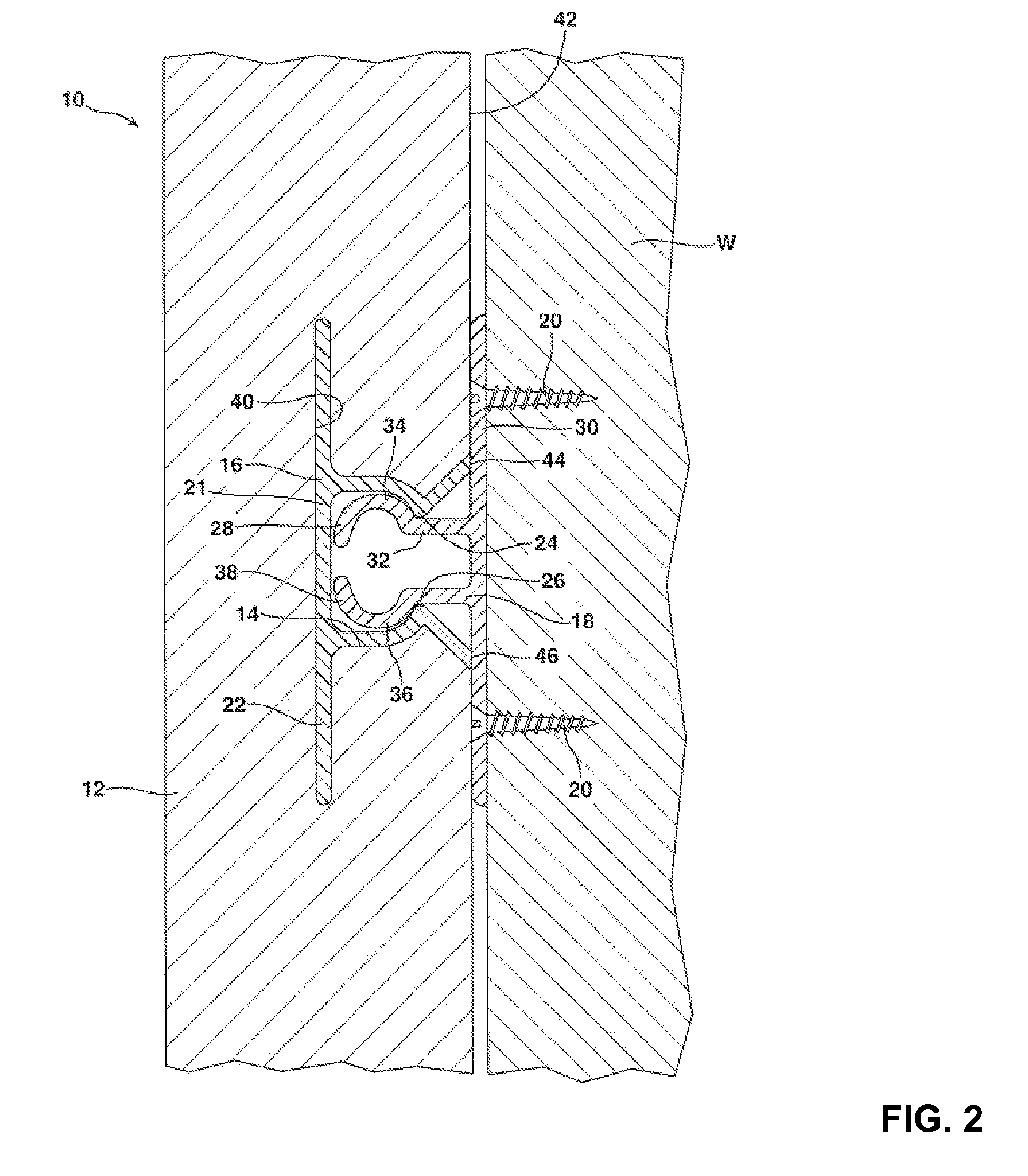
[0008]In accordance with the purposes of the present invention as described herein, a wall panel is provided for securing to a wall. The wall panel comprises a panel body having a periphery, a front face and a rear face. A cavity is included in the rear face of the panel body, preferably located interiorly of the periphery. A first mounting member is received or embedded fully within the cavity so as not to project beyond the rear face of the panel body. The wall panel further includes a second mounting member adapted to be secured to a wall. The first and second mounting members are frictionally connected together to secure the wall panel to the wall, such that the connectors lie entirely within the cavity enabling the rear surface of the panel to be spaced closely up to the wall. In accordance with an additional aspect of the present invention the panel body is solid and planar and the first and second mounting members are resilient. A panel body may have multiple cavities and first mounting members disposed therein. This construction is particularly well suited for composite panels, and placing the cavities and mounting members away from the periphery more easily conceals the mounting members.
[0009]In accordance with an additional aspect of the present invention a method is provided of covering a wall with a wall panel. That method comprises the steps of locating a position on a wall for a second mounting member; attaching said second mounting member to the wall at that position, aligning a first mounting member in the wall panel over the second mounting member and connecting the second mounting member and the first mounting member together within a cavity in the wall panel in order to secure the wall panel to the wall. Due to frictional engagement, eg of resilient mounting members, the panels are easily removable if needed.

Problems solved by technology

When applied to a ceiling, if an adhesive has a high enough initial tack to hold the panels from falling, small adjustments in the lateral placement of the panels are not possible and the overall installed quality of the wall panels due to varying gaps between panels is undesirably low.
Providing a wall or floor with such cavities or channels is a time consuming and relatively expensive process.
While this mounting system does not require providing channels or grooves in the underlying wall, convex wall panels are not desired by many customers or suited for many applications.
However, in neither of these designs does the concavity in the wall attachments have an embedded mounting member; these panels tend not to be easily removable.

Method used


Image

  • Push mount wall panel
  • Push mount wall panel
  • Push mount wall panel

Examples


Embodiment Construction

[0017]Unless otherwise defined, all technical and scientific terms used herein have the same meaning as commonly understood by one of ordinary skill in the art to which this invention belongs. The terminology used in the description of the invention herein is for describing particular embodiments only and is not intended to be limiting of the invention. As used in the description of the invention and the appended claims, the singular forms “a,”“an,” and “the” are intended to include the plural forms as well, unless the context clearly indicates otherwise. All references cited herein, including published or corresponding U.S. or foreign patent applications, issued U.S. or foreign patents, or any other references, are each incorporated by reference in their entireties, including all data, tables, figures, and text presented in the cited references. In the drawings, the thickness of the lines, layers, and regions may be exaggerated for clarity.

[0018]Unless otherwise indicated, all numb...


PUM


Abstract

A wall panel is provided including a panel body having a front face and a rear face. A cavity is provided in the rear face of the panel body. A first mounting member is received fully within that cavity so as to not project beyond the rear face of the panel body. The wall panel system also includes a second mounting member that is secured to the wall. The first and second mounting members are connected together to attach the wall panel to the wall.

Description

TECHNICAL FIELD[0001]The present invention relates generally to wall panel systems and more particularly to a novel push mount wall panel that is removable, inexpensive to produce and easy to use.BACKGROUND OF THE INVENTION[0002]Wall panel systems for decorating walls of structures such as offices and homes are well known in the art. Such systems rely upon decorative and functional wall panels that are mounted to the wall of a structure at selected locations in order to provide the desired aesthetic effect. Wall panels may be made from any number of materials including acoustical insulating materials of a type well known in the art.[0003]In one prior art approach the wall panels are secured to the underlying wall of the structure by using a perimeter adhesive that is applied to the rear of the wall panel and / or the underlying wall structure. While such a panel and mounting system is relatively inexpensive to manufacture and relatively easy to install, it should be appreciated that t...

Claims


Application Information

Patent Timeline
IPC IPC(8): E04B2/30E04B2/72
CPCE04F13/0835
Inventor KLIEGLE, DENNIS R.BECKER, CRAIG A.PINNOW, JOHN W.
Owner OWENS CORNING INTELLECTUAL CAPITAL LLC
Why Eureka
Try Eureka