Connector for panel members

US20110303813A1Inactive Publication Date: 2011-12-15LIJESNIC MLADEN

Image

  • Connector for panel members
  • Connector for panel members
  • Connector for panel members

Examples


Embodiment Construction

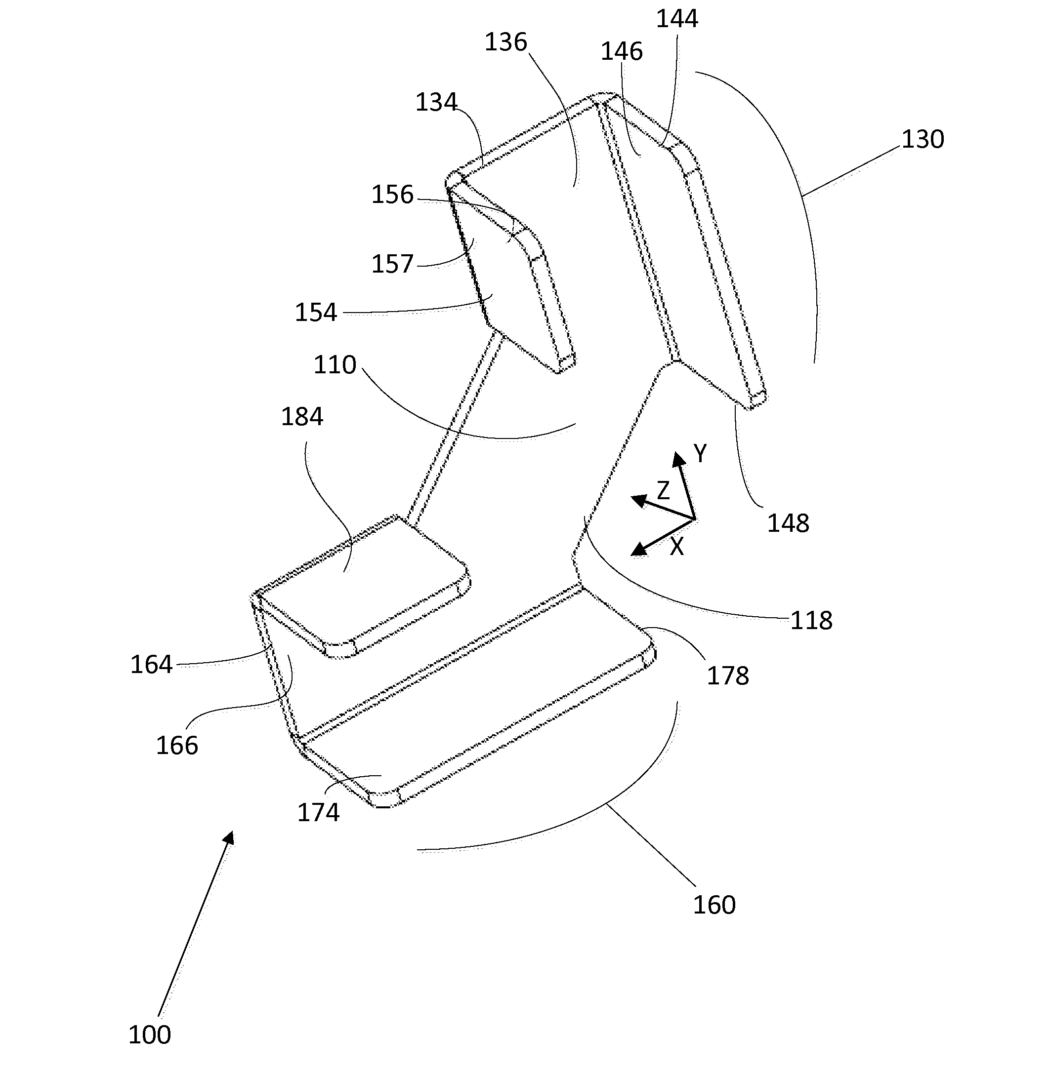
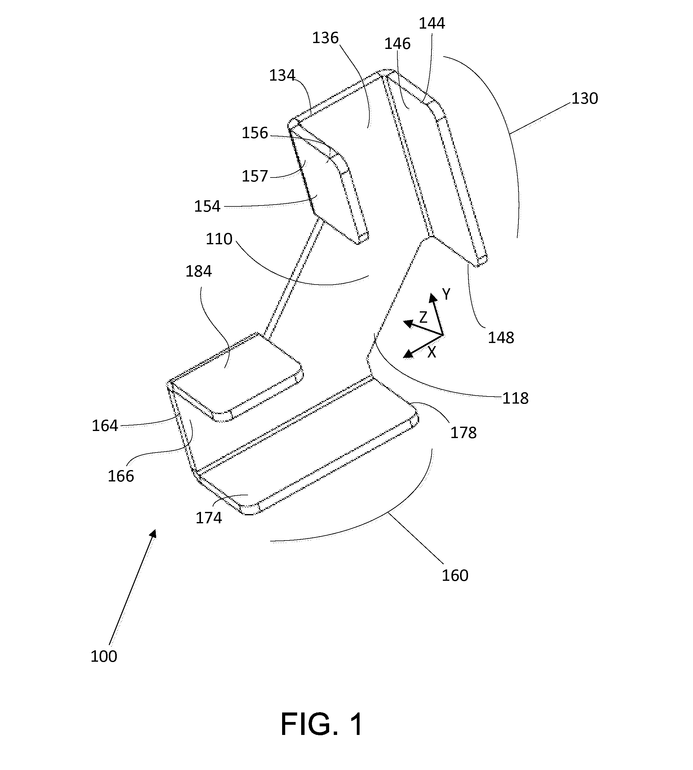
[0028]With reference to FIG. 1, there is shown a connector 100 in accordance with embodiments of the invention. The connector 100 comprises a panel support portion 110. First arm 130 and second arm 160 each extend outwardly from support portion 110.

[0029]First arm 130 includes a base 134 connected to and extending outwardly from support portion 110. On first arm 130, outer wall 144 and inner wall 154 extend away from base 134 in opposing positions, such that base 134, outer wall 144 and inner wall 154 define a first arm channel 136. Similarly, second arm 160 includes a base 164 connected to and extending outwardly from support portion 110. On second arm 160, outer wall 174 and inner wall 184 extend away from base 164 in opposing positions, such that base 164, outer wall 174 and inner wall 184 define a second arm channel 166.

[0030]The first and second arm channels 136, 166 can be generally U-shaped such that they can each fit about and provide stability to a panel member, such as a b...


PUM


Abstract

Aspects of the invention are directed to a connector that connects a first flat member and a second flat member. The connector can include a support portion, a first arm, connected to the support portion, and defining a first arm channel. The connector can also include a second arm, connected to the support portion, and defining a second arm channel, the second arm being apart from the first arm. An opening is defined, in part, by an edge of the support portion, and edge of the first arm and an edge of the second arm. Also, the first arm channel an the second arm channel and the support portion are shaped and configured such that the first flat member can be positioned, in part, within the first arm channel, and extend through the opening, and the second flat member can be positioned, in part, in the second arm channel.

Description

CROSS-REFERENCE TO RELATED APPLICATIONS[0001]This application is a continuation of International Patent Application No. US2011 / 037556, filed on May 23, 2011, currently pending, which claims the benefit of U.S. Provisional Patent Application No. 61 / 346,965, filed May 21, 2010, the contents of both applications being incorporated herein by reference.BACKGROUND OF THE INVENTION[0002]1. Field of the Invention[0003]Embodiments of the invention are directed to connectors for connecting panel members, and, in particular, connectors for connecting panel members to form furniture or other pieces.[0004]2. Description of Related Art[0005]It is a common occurrence to assemble multiple panel members, such as, for example, wooden boards or panels, into structural pieces, such as furniture. For example, it is typical for furniture companies to ship furniture pieces unassembled, with makers shipping panels, and hardware for connecting the panels, to stores. The furniture pieces are then either asse...

Claims


Application Information

Patent Timeline
15 Dec 2011
Publication
US20110303813A1
IPC
A47B96/06
CPC
Y10T403/4602; A47B47/0033; F16B12/50; Y10T403/34
Inventors
LIJESNIC, MLADEN