Module component

Active Publication Date: 2019-03-07
MURATA MFG CO LTD
View PDF3 Cites 0 Cited by
  • Summary
  • Abstract
  • Description
  • Claims
  • Application Information

AI Technical Summary

Benefits of technology

[0043]With this structure, since the sub-electrode and the first main electrode or the second main electrode are connected only by the conductive bonding member in one substrate, a wiring pattern connecting the sub-electrode and the first main electrode or the second main electrode is not required to be

Problems solved by technology

Furthermore, labor and time are required to form the wirings and the electrodes in and on the circuit substrate in accordance with each design change.
More

Method used


Image

  • Module component
  • Module component
  • Module component

Examples


embodiment 1

Preferred Embodiment 1

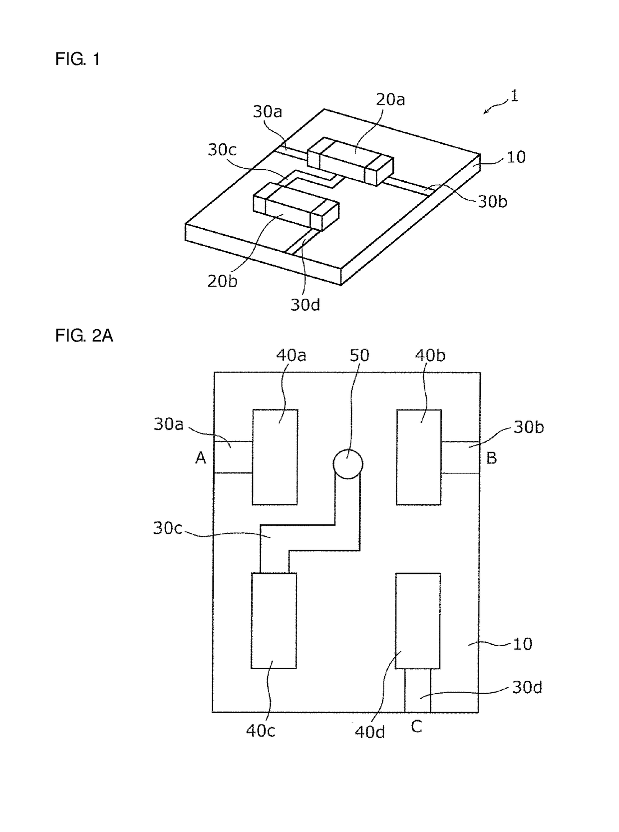
[0082]Preferred Embodiment 1 of the present invention will be described below with reference to FIGS. 1 to 3B. A module component 1 mounted to a substrate 40 is described in the present preferred embodiment.

[0083]FIG. 1 is a conceptual view illustrating a configuration of the module component 1 according to the present preferred embodiment.

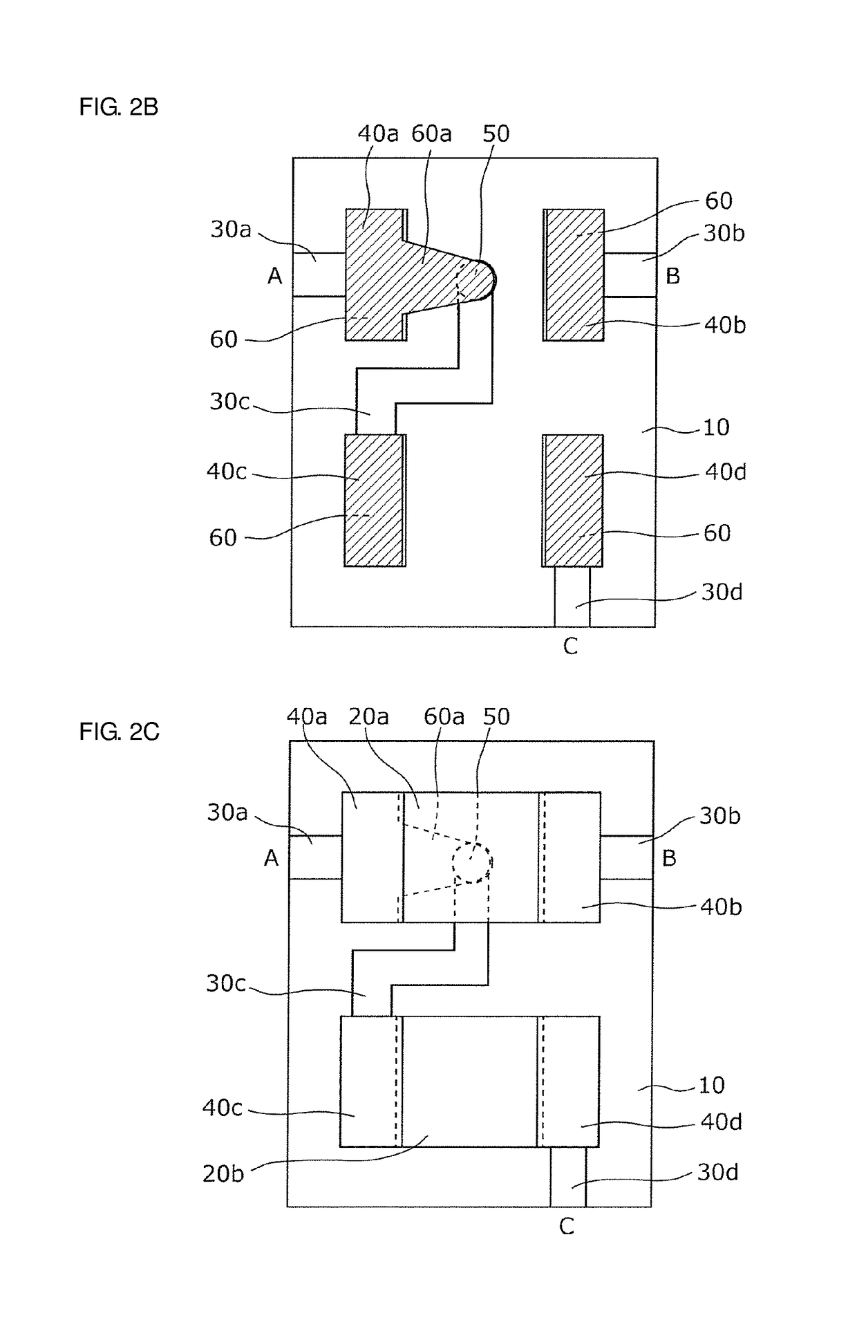
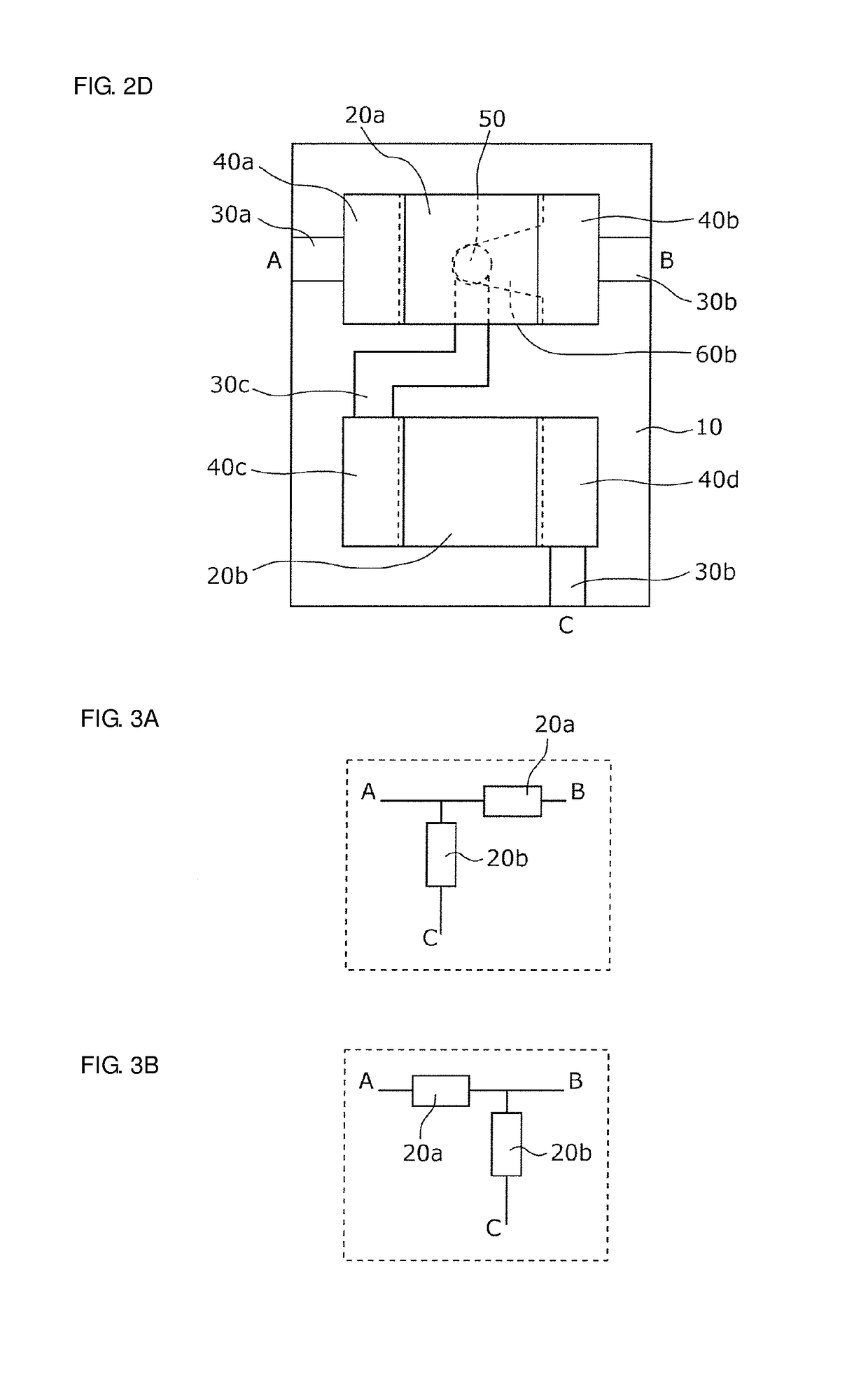
[0084]On or in a principal surface of a substrate 10, the module component 1 includes, as illustrated in FIG. 1, a first mount component 20a, a second mount component 20b, and wirings 30a, 30b, 30c and 30d, and, as illustrated in FIG. 2A, a first main electrode 40a, a second main electrode 40b, a third main electrode 40c, a fourth main electrode 40d (see FIG. 2A), and a sub-electrode 50 (see FIG. 2A)

[0085]The substrate 10 is preferably, for example, a printed substrate or an LTCC (Low Temperature Co-fired Ceramics) substrate.

[0086]The first mount component 20a and the second mount component 20b are preferably, for example, co...

embodiment 2

Preferred Embodiment 2

[0114]Preferred Embodiment 2 of the present invention will be described below with reference to FIGS. 4A to 4C.

[0115]FIG. 4A is a plan view illustrating one example of an electrode pattern in a module component according to the present preferred embodiment. FIGS. 4B and 4C are each a plan view illustrating an example of a configuration of the module component according to the present preferred embodiment in which a first mount component and a second mount component are mounted.

[0116]The module component according to the present preferred embodiment is different from the module component 1 according to Preferred Embodiment 1 in that the sub-electrode 50 is defined by a plurality of sub-electrodes, i.e., a first sub-electrode 50a and a second sub-electrode 50b. The remaining configuration is the same as or similar to that in the module component 1 according to Preferred Embodiment 1, and thus detailed description of the remaining configuration is omitted.

[0117]As...

embodiment 3

Preferred Embodiment 3

[0123]Preferred Embodiment 3 of the present invention will be described below with reference to FIGS. 5A to 5C.

[0124]FIG. 5A is a plan view illustrating one example of an electrode pattern in a module component according to the present preferred embodiment. FIGS. 5B and 5C are each a plan view illustrating an example of a configuration of the module component according to the present preferred embodiment in which a first mount component and a second mount component are mounted.

[0125]The module component according to the present preferred embodiment is different from the module component 1 according to Preferred Embodiment 1 in that a sub-electrode 50c and a sub-electrode 50d are provided at positions not overlapping the first mount component 20a and the second mount component 20b when viewing the module component according to the present preferred embodiment in plan.

[0126]More specifically, as illustrated in FIG. 5A, the sub-electrode 50c is disposed between th...


PUM


Abstract

A module component includes a substrate; first, second, third and fourth main electrodes on or in a principal surface of the substrate; a sub-electrode located between two of the four main electrodes and connected to one of the four main electrodes by a solder; a first mount component mounted to the first and second main electrodes; and a second mount component mounted to the third and fourth main electrodes; wherein an area of the sub-electrode is smaller than an area of each of the first, second, third and fourth main electrodes.

Description

CROSS REFERENCE TO RELATED APPLICATIONS[0001]This application claims the benefit of priority to Japanese Patent Application No. 2016-099998 filed on May 18, 2016 and is a Continuation Application of PCT Application No. PCT / JP2017 / 014160 filed on Apr. 4, 2017. The entire contents of each application are hereby incorporated herein by reference.BACKGROUND OF THE INVENTION1. Field of the Invention[0002]The present invention relates to a module component.2. Description of the Related Art[0003]In the fields of electrical devices and communication devices, a module component including a mount component mounted to a circuit substrate has been developed (see, e.g., Japanese Unexamined Patent Application Publication No. 2010-67989).[0004]In a module component disclosed in Japanese Unexamined Patent Application Publication No. 2010-67989, a circuit configuration including electronic components, wirings, etc. is designed in advance. To obtain the designed circuit configuration, the wirings are ...

Claims


Application Information

Patent Timeline
IPC IPC(8): H05K1/11H05K1/18H05K1/02
CPCH05K1/113H05K1/18H05K1/0231H05K1/115H05K1/029H05K1/111H05K3/3442H05K2201/0305H05K2201/10636H05K2203/173Y02P70/50
Inventor NISHIKAWA, HIROSHI
Owner MURATA MFG CO LTD
Why Eureka
Try Eureka