Connector

a technology of connecting rods and connecting rods, applied in the direction of incorrect coupling prevention, coupling device connection, electrical apparatus, etc., can solve the problems of lock arm warp and deformation, mechanical detection technique of detecting rods cannot be adopted, and the detecting member cannot move smoothly, etc., to achieve satisfactory connection sound

Active Publication Date: 2019-12-03
SUMITOMO WIRING SYST LTD
View PDF17 Cites 0 Cited by
  • Summary
  • Abstract
  • Description
  • Claims
  • Application Information

AI Technical Summary

Benefits of technology

[0008]When the housing is connected properly, the lock arm resiliently returns and the colliding portion contacts the wall surface of the housing or the mating housing to produce a connection sound. The connection sound provides an audible detection that the housings have been connected properly. The colliding portion is sized to project farther forward than the front end of the resilient arm when the detector is at the detection position. Therefore, a sufficient striking margin (hitting area) to strike the wall surface can be ensured in a front-rear direction. Thus, satisfactory connection sound can be generated even without enlarging the striking margin in a deflecting direction of the lock arm, and the lock arm will not warp and deform. As a result, the detector can move smoothly from the standby position to the detection position with respect to the lock arm and both mechanical detection of the detector and auditory detection of the colliding portion can be exhibited satisfactorily. Further, the colliding portion is arranged at both sides of the front end part of the resilient arm and projects farther forward than the front end of the resilient arm. Thus, the front part of the resilient arm is protected from both sides by the colliding portion and external matter cannot interfere with the front end part of the resilient arm in a manner that could inadvertently unlock the resilient arm from the lock arm.

Problems solved by technology

However, the padding of the inner surface of the hook can cause the lock arm to warp and deform so that the hook inclines up toward the front when the connectors are connected properly.
Thus, the detecting member cannot move smoothly from the standby position to the detection position on the upper surface of the lock arm, thereby causing a problem that the mechanical detection technique by the detecting member cannot be adopted.

Method used


Image

  • Connector
  • Connector
  • Connector

Examples


Embodiment Construction

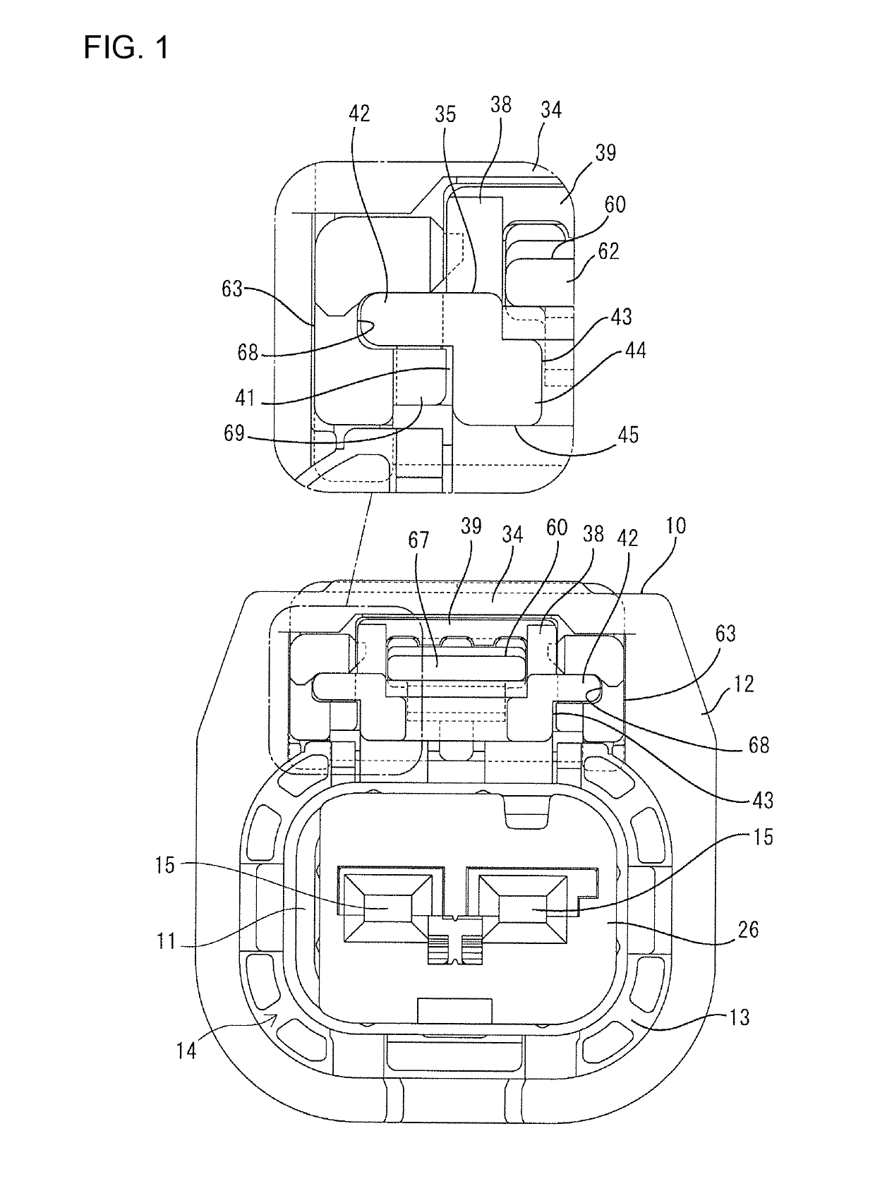
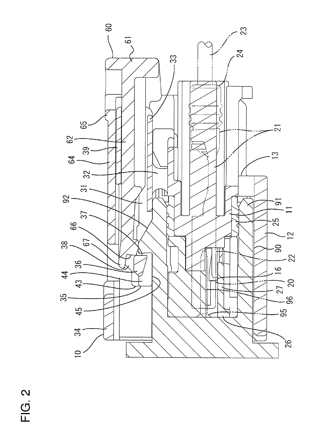
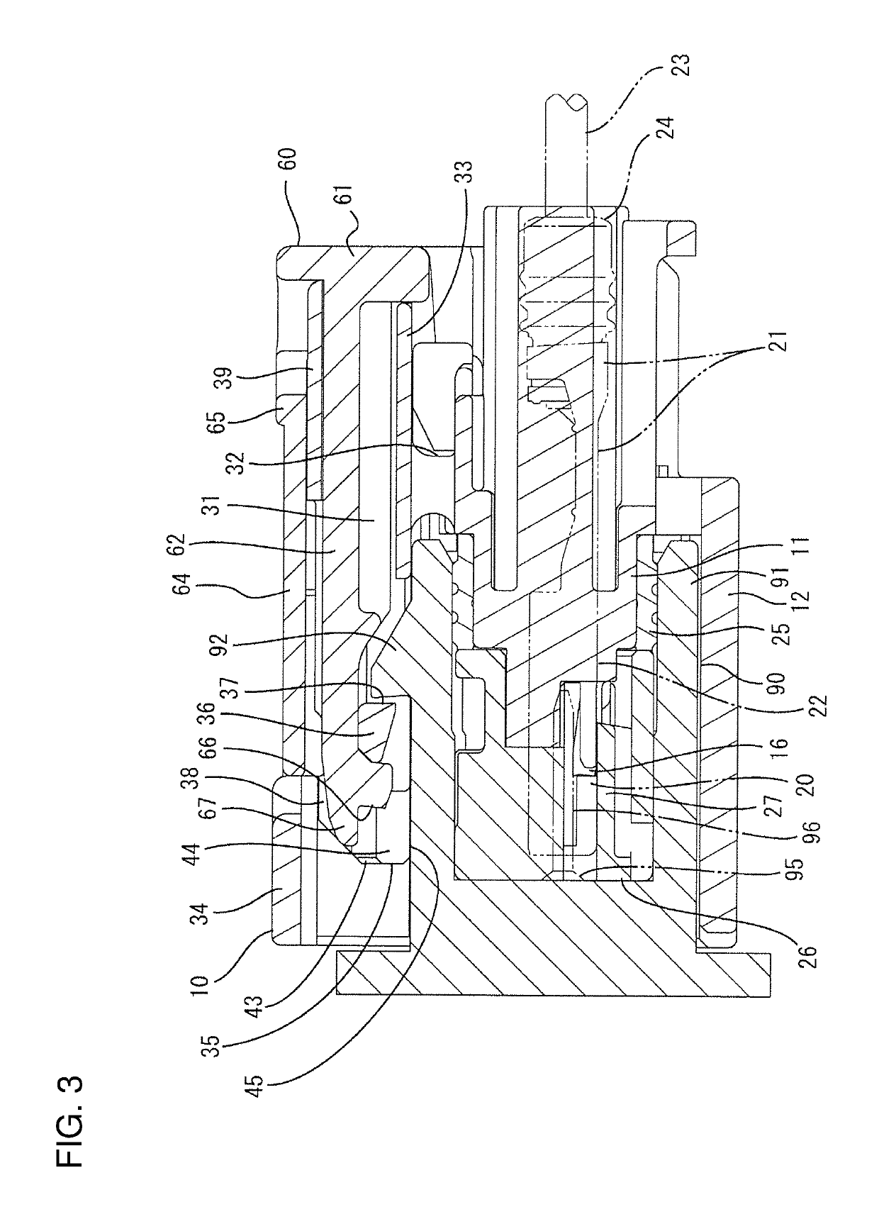
[0016]A connector of one embodiment includes a housing 10 and a detector 60. The housing 10 is connectable to a mating housing 90. The detector 60 is mounted in the housing 10 movably between a standby position and a detection position. Note that, in the following description, sides of the housings 10, 90 facing each other when connection is started are referred to as the fronts concerning a front-rear direction. A vertical direction is based on figures except FIGS. 4 and 6.

[0017]The mating housing 90 is made of synthetic resin and includes a tubular receptacle 91 projecting forward. A lock 92 projects on the upper surface of an upper wall of the receptacle 91. The front surface of the lock 92 is inclined rearwardly toward a projecting end, and the rear surface thereof is formed into a claw shape substantially extending along the vertical direction. Male tabs 96 of mating terminal fittings 95 project into the receptacle 91.

[0018]The housing 10 is made of synthetic resin and includes...


PUM


Abstract

A housing (10) includes a lock arm (31) for resiliently connecting and holding a mating housing (90). A detector (60) is movable to a standby position and a detection position with respect to the lock arm (31), and includes a resilient arm (62) to be resiliently locked by the lock arm (31) at the standby position. The lock arm (31) includes colliding portions (43) arranged at both sides of a front part of the resilient arm (62) and projecting farther forward than a front end of the resilient arm (62) and configured to contact a wall surface of the housing (10) or the mating housing (90) by a resilient returning movement of the lock arm (31) when the detector (60) is at the detection position.

Description

BACKGROUND[0001]Field of the Invention.[0002]The present invention relates to a connector.[0003]Description of the Related Art.[0004]Japanese Unexamined Patent Publication No. H08-321352 discloses a connector that includes a female connector and a male connector that are connectable to each other. The male connector includes a claw-like engaging projection on an outer wall of a receptacle. The female connector includes a seesaw-like lock arm at a position facing the engaging projection. The lock arm has a striking margin to move resiliently over the engaging projection and be struck against the outer wall of the receptacle on a back side of the engaging projection when the connectors are connected properly. This striking margin is formed by padding an inner surface of a hook on a tip part of the lock arm.[0005]A connected state can be determined by auditory detection of a connection sound (locking sound, colliding sound) caused by the striking margin, and a detecting member may be a...

Claims


Application Information

Patent Timeline
Patent Type & Authority Patents(United States)
IPC IPC(8): H01R13/627H01R13/64
CPCH01R13/6272H01R13/64H01R13/639
Inventor YAMANAKA, WATARUHORIUCHI, HIDEFUMI
Owner SUMITOMO WIRING SYST LTD
Why Eureka
Try Eureka