Rack-Based Uninterruptible Power Supply

a power supply and uninterruptible technology, applied in emergency power supply arrangements, instruments, transportation and packaging, etc., can solve the problem of difficulty in providing a constant source of power, and achieve the effect of improving the reliability of the system

Active Publication Date: 2011-12-15
MICROSOFT TECH LICENSING LLC
View PDF50 Cites 120 Cited by
  • Summary
  • Abstract
  • Description
  • Claims
  • Application Information

AI Technical Summary

Problems solved by technology

Providing a constant source of power, however, can be difficult because power providers occasionally experience power outages.
Providing a backup power supply to a data center to protect against such a power outage can be beneficial, but is not without its own problems, such as the cost involved in building and maintaining such a backup power supply for the data center.

Method used


Image

  • Rack-Based Uninterruptible Power Supply
  • Rack-Based Uninterruptible Power Supply
  • Rack-Based Uninterruptible Power Supply

Examples


Embodiment Construction

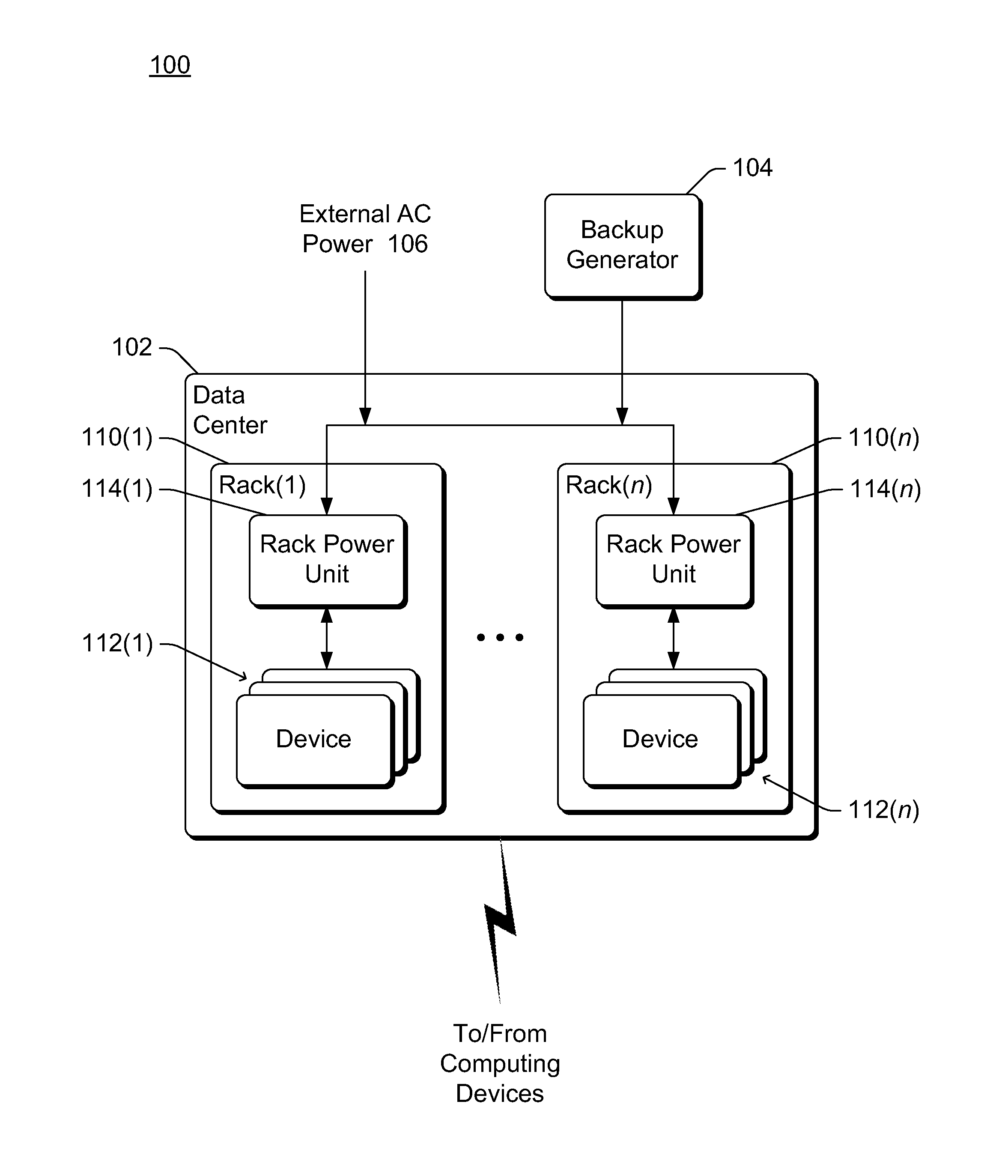
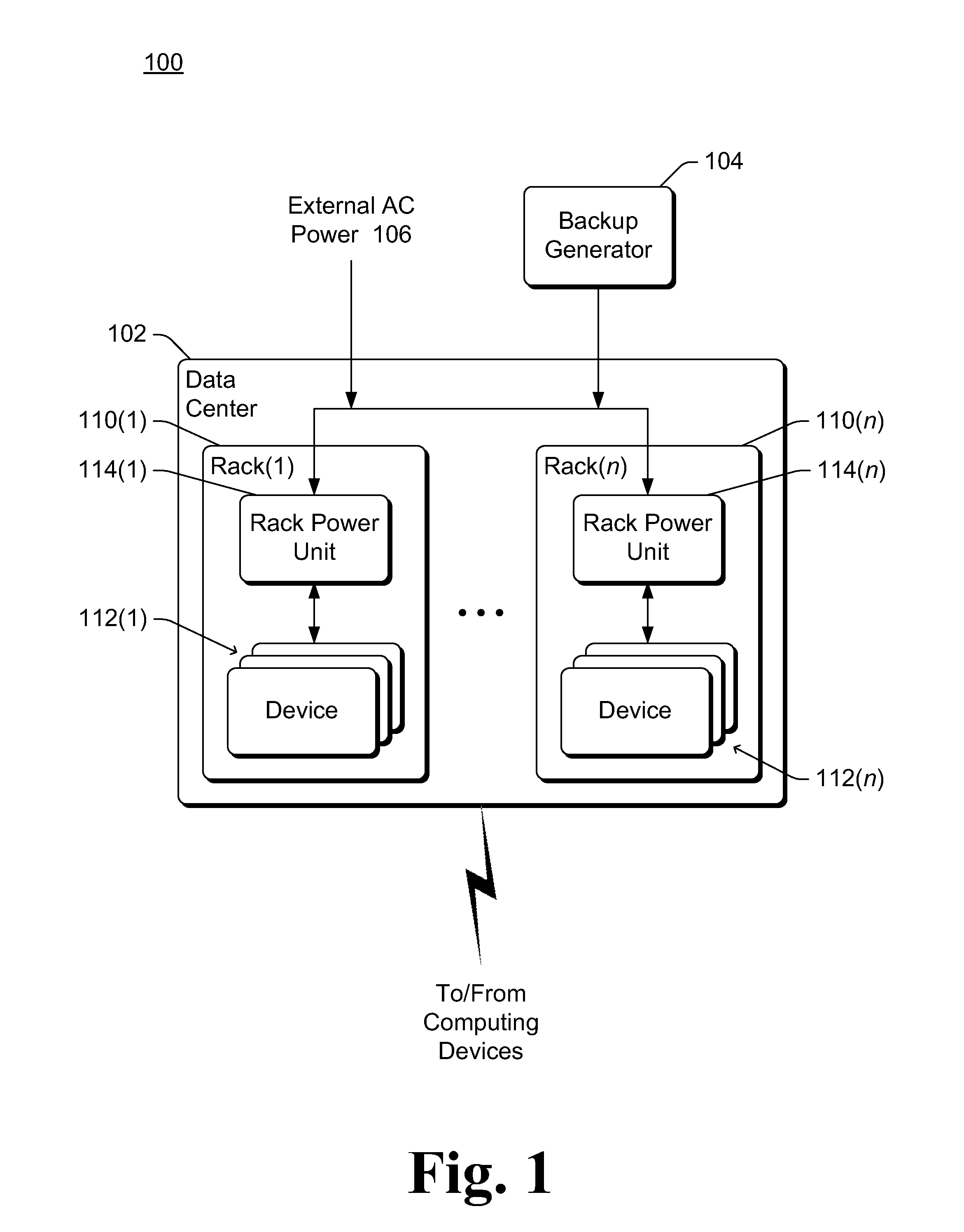
A rack-based uninterruptible power supply is discussed herein. A data center includes multiple computing devices and optionally other networking devices that are located within a device rack. AC (alternating current) power is provided to the data center from an external power source, and also from a backup generator in the event of a loss of power from the external power source. Additionally, each device rack has a rack power unit that receives the AC power and converts the AC power to DC (direct current) power, which in turn is provided to the devices located within that device rack. Each rack power unit also includes one or more battery packs that provide power to the devices within that rack during a time period between the loss of power from the external AC power source and the backup generator becoming operational and providing AC power to the data center. Each rack power unit can also provide additional functionality, such as providing additional DC power from the battery pack...


PUM


Abstract

A rack power unit is configured to be inserted into a device rack of a data center. The rack power unit includes one or more power supplies and one or more battery packs. The one or more power supplies are each configured to receive power (e.g., AC power) when the apparatus is in the device rack, and convert the received power to a DC power. The one or more power supplies are further configured to output the DC power to a DC power bus of the device rack. The one or more battery packs are each configured to provide, in response to an interruption in the received power, DC power to the DC power bus of the device rack.

Description

BACKGROUNDSituations arise where it is desirable to have a large number of computers operating together at a particular location to provide a service, such as data centers or server farms providing services over the Internet. Oftentimes it is desirable to have a constant source of power at such locations so that the computers and other devices operating at that location continue functioning. Providing a constant source of power, however, can be difficult because power providers occasionally experience power outages. Providing a backup power supply to a data center to protect against such a power outage can be beneficial, but is not without its own problems, such as the cost involved in building and maintaining such a backup power supply for the data center.SUMMARYThis Summary is provided to introduce a selection of concepts in a simplified form that are further described below in the Detailed Description. This Summary is not intended to identify key features or essential features of...

Claims


Application Information

Patent Timeline
Patent Type & Authority Applications(United States)
IPC IPC(8): H02J7/34H02J9/08
CPCG06F1/263G06F1/30H05K7/1492H05K7/1457H02J9/08
Inventor PETERSON, ERIC C.HARRIS, SHAUN L.BELADY, CHRISTIAN L.SHAKIB, DARREN A.OLARIG, SOMPONG PAULWIRTZ, FRANK J.
Owner MICROSOFT TECH LICENSING LLC
Why Eureka
Try Eureka