Illumination device and liquid crystal display device

illumination device technology, applied in the field of backlight, can solve the problem of low contrast (dynamic range) of images displayed by such a liquid crystal display device, and achieve the effect of reducing uneven luminan

Inactive Publication Date: 2011-12-15
SHARP KK
View PDF3 Cites 21 Cited by
  • Summary
  • Abstract
  • Description
  • Claims
  • Application Information

AI Technical Summary

Benefits of technology

This arrangement restrains luminance unevenness and color unevenness so that a luminance distribution becomes constant, thereby resulting in that it is possible to provide a high-quality illumination device.
As described above, in order to achieve the above object, an illumination device of the present invention is an illumination device capable of adjusting luminance per light-emitting region and includes: first partition walls by which a plurality of light-emitting regions are separated; light sources each for emitting light having different wavelengths, the light sources being provided in a respective of the plurality of light-emitting regions; second partition walls which are provided higher than the first partition walls and which enclose the plurality of light-emitting regions; optical means for diffusing the light emitted from each of the light sources, the optical means being supported by the second partition walls; and a diffusion section for diffusing the light emitted from the each of the light sources, the diffusion section being fixed on the first partition walls so as to be disposed on upper sides of the plurality of light-emitting regions.

Problems solved by technology

However, there is a problem that an image displayed by such a liquid crystal display device has low contrast (dynamic range) due to a display method of the liquid crystal display device, in comparison with an image displayed by the CRT.
However, the above arrangement causes such a problem that the irradiating light is blocked by the partition wall 102 provided between the adjacent illumination regions and therefore a vicinity of an area above the partition wall 102 becomes dark.

Method used


Image

  • Illumination device and liquid crystal display device
  • Illumination device and liquid crystal display device
  • Illumination device and liquid crystal display device

Examples


embodiment 1

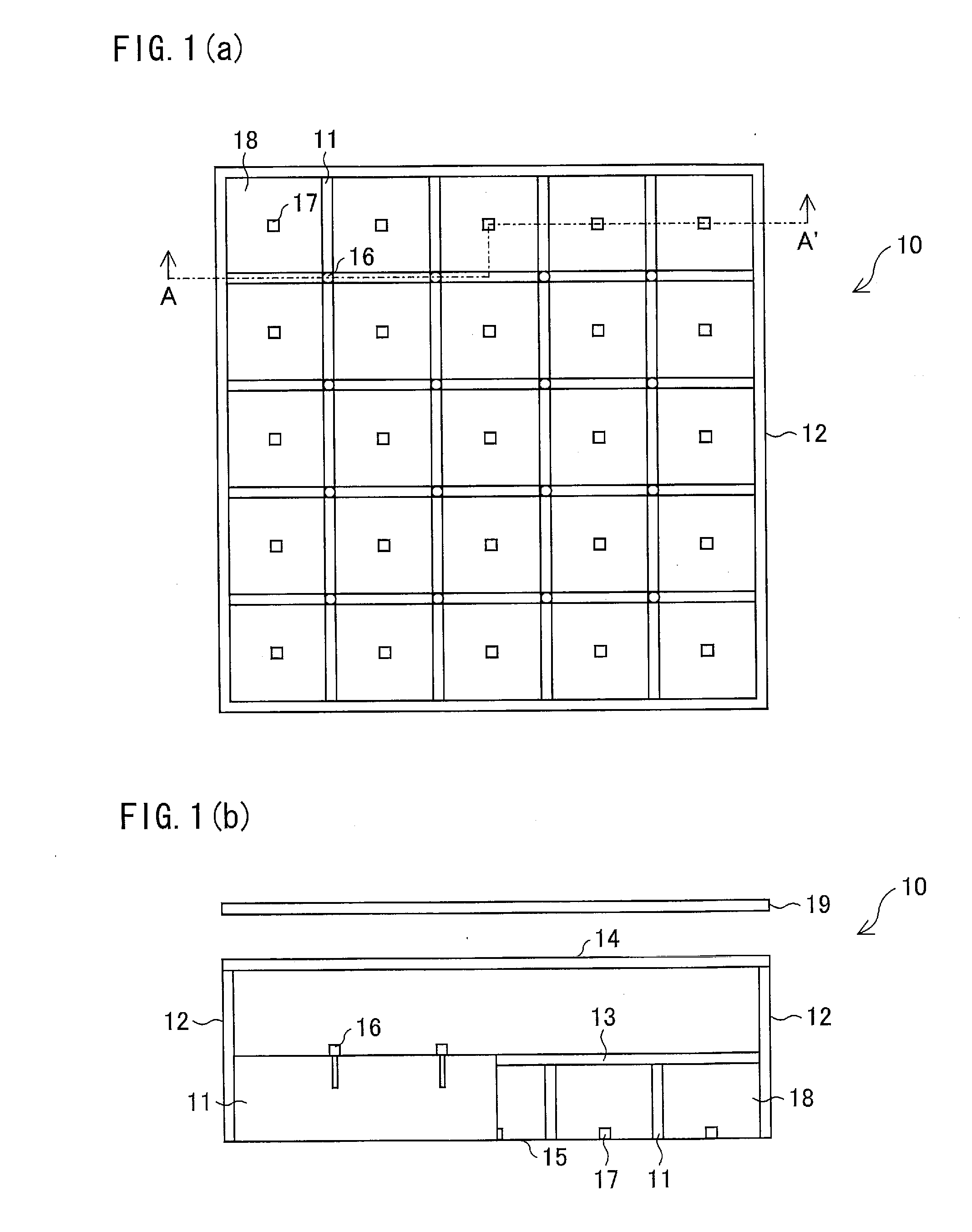
One embodiment of the present invention is described below with reference to FIG. 1(a) and FIG. 1(b).

FIG. 1(a) is a plane view illustrating an illumination device 10 according to one embodiment of the present invention. Further, FIG. 1(b) is a cross-sectional view taken along line A-A′ of FIG. 1(a).

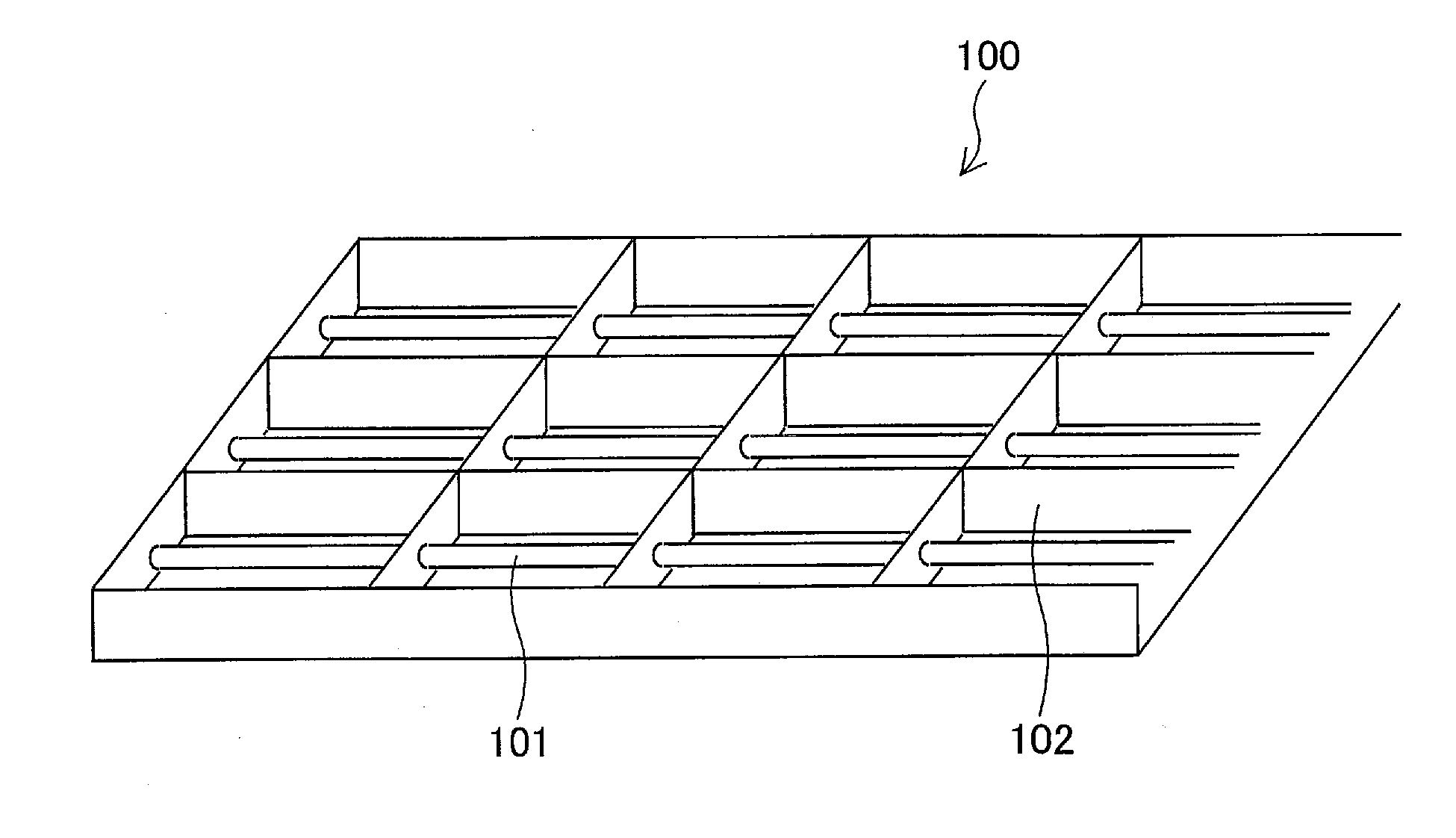
As illustrated in FIG. 1(a), the illumination device 10 includes: first partition walls 11 for dividing the illumination device 10 into a plurality of light source blocks (light-emitting regions) 18; and second partition walls 12 surrounding the illumination device 10 so as to enclose the plurality of light source blocks 18. The first partition walls 11 are disposed in a lattice manner over the illumination device 10. In the present embodiment, a pitch of the light source block 18 (i.e., a length of a side of one cell in the lattice) is 28 mm.

In each of the light source blocks 18 is provided a light source 17 that emits light having different wavelengths. The light source blocks 18 are in...

embodiment 2

are the same as those in Embodiment 1, and therefore are not described here.

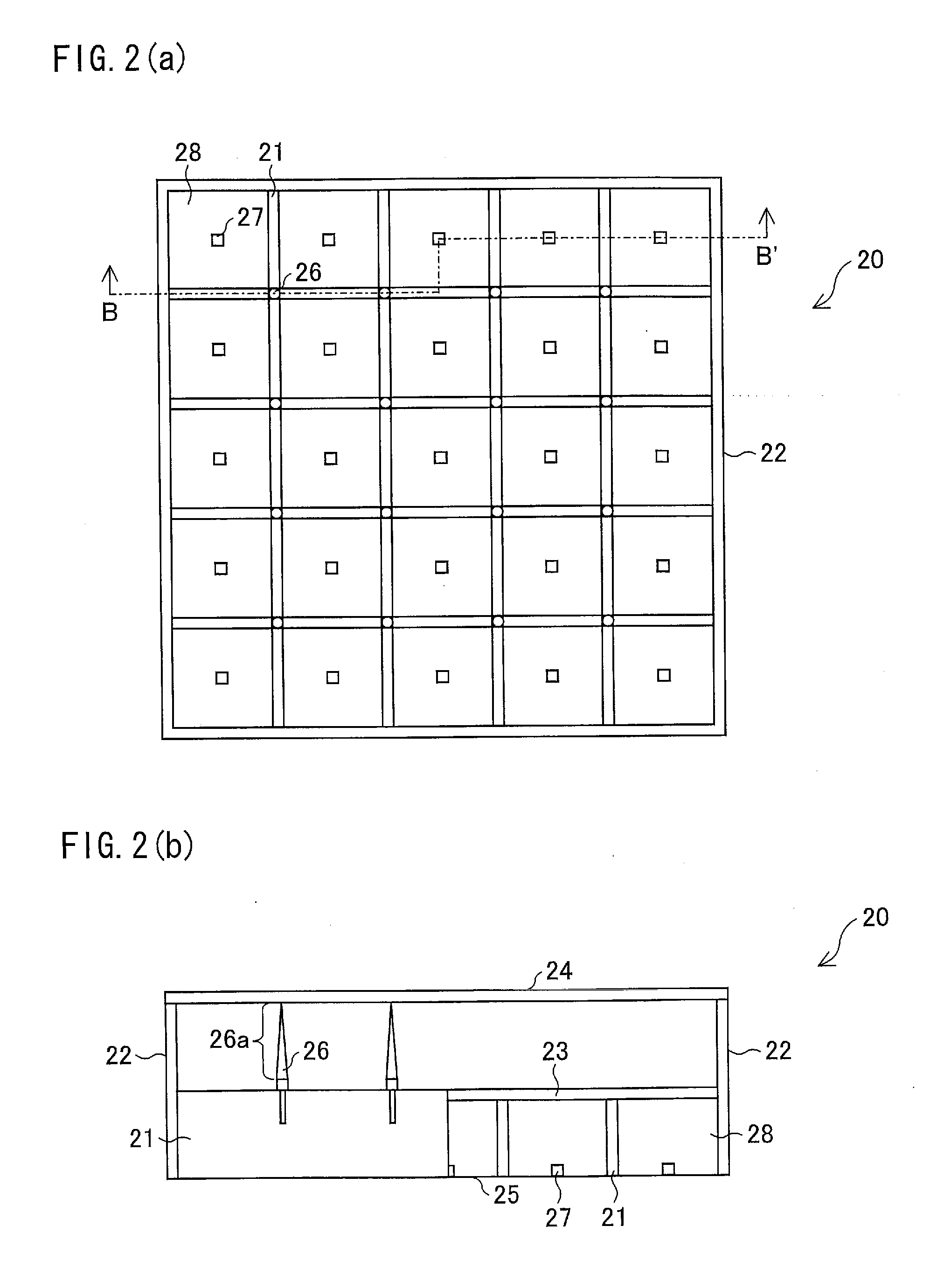
In the illumination device 20 in FIG. 2(b), a first partition wall 21, a second partition wall 22, a diffusion plate 23, an optical section 24, a reflecting plate 25, a light source 27 and a light source block 28 respectively correspond to the first partition wall 11, the second partition wall 12, the diffusion plate 13, the optical section 14, the reflecting plate 15, the light source 17 and the light source block 18 in the illumination device 10 in FIG. 1(b).

On top portions of first partition walls 21 are provided a plurality of holes at respective intersections of the first partition walls 21 that intersect each other substantially at right angle. The top portions of the first partition walls 21 have contact with the diffusion plate 23. In the diffusion plate 23, through holes are provided at positions each corresponding to each of the plurality of holes provided on the top portions of the first partition...

embodiment 3

is different from Embodiment 2 in shape of a side surface of the first partition wall. Other arrangements are the same as those in Embodiment 2 and therefore are not explained here.

In the illumination device 30 in FIG. 3(b), a second partition wall 32, a diffusion plate 33, an optical section 34, a reflecting plate 35, a fixing pin 36, a light source 37 and a light source block 38 respectively correspond to the second partition wall 22, the diffusion plate 23, the optical section 24, the reflecting plate 25, the fixing pin 26, the light source 27 and the light source block 28 in FIG. 2(b).

A side surface 31a of the first partition wall 31 has a recessed curved-surface shape from a top surface of the first partition wall 31 toward a bottom surface of the first partition wall 31. The top surface is a contact surface of the first partition wall 31 which surface has contact with the diffusion plate 33, and the bottom surface is a contact surface of the first partition wall 31 which surfa...


PUM

PropertyMeasurementUnit
lengthaaaaaaaaaa
diffused-light transmittanceaaaaaaaaaa

Abstract

An illumination device 10 includes a diffusion plate 13 for diffusing light emitted from light sources 17, which diffusion plate 13 is fixed on first partition walls 11 and provided on upper sides of light source blocks 18. The arrangement makes it possible to provide a high-quality illumination device and a high-quality liquid crystal display device in each of which unevenness in luminance and color is restrained so that a luminance distribution becomes constant.

Description

This Nonprovisional application hereby incorporate by reference the entire contents of Patent Application No. 2007-315191 filed in Japan on Dec. 5, 2007.TECHNICAL FIELDThe present invention relates to a backlight including a plurality of light sources and a liquid crystal display device including the backlight.BACKGROUND ARTLiquid crystal display devices have such features that they are reduced in thickness, their power consumption is low, and they have a high resolution. Further, along with an increase in screen size of these liquid crystal display devices due to development of manufacturing techniques, the liquid crystal display devices have become widely used in a television field that used to employ cold-cathode tubes (CRT) mainly. However, there is a problem that an image displayed by such a liquid crystal display device has low contrast (dynamic range) due to a display method of the liquid crystal display device, in comparison with an image displayed by the CRT. On this accoun...

Claims


Application Information

Patent Timeline
Patent Type & Authority Applications(United States)
IPC IPC(8): G02F1/1335F21V1/00
CPCG02F1/133603G02F1/133608G02F1/133606G02F1/133605
Inventor TANAKA, ATSUYUKIMASUDA, TAKESHISUMINOE, SHINJIITOH, KOHJI
Owner SHARP KK
Why Eureka
Try Eureka