Double-pronged flex hinge mechanism for eyeglasses temple arms

a hinge mechanism and eyeglasses technology, applied in the field of glasses frames, can solve the problems of poor design, inconvenient use, and inability to meet the needs of users, and achieve the effects of simple structure, convenient assembly and clever design

Inactive Publication Date: 2011-12-15
EAGLE INT INDAL
View PDF1 Cites 8 Cited by
  • Summary
  • Abstract
  • Description
  • Claims
  • Application Information

AI Technical Summary

Benefits of technology

[0014]The present invention can be easily assembled without any screws. Simple in structure, cleverly designed, and easy to produce, it makes fast and efficient production possible. It is also durable and reliable.

Problems solved by technology

Screws, which are vital in the articulation of the frame front and the temples, can easily get loose and fell out, resulting in repair of the glasses before they can be used again and causing inconvenience to the users.
Poor in design and technologically backward, the connecting members, which serve for attaching temple arms to frame fronts, of most of the existing eyewear require improvement.
This poses pressing technological problems for eyewear technicians to solve.

Method used


Image

  • Double-pronged flex hinge mechanism for eyeglasses temple arms
  • Double-pronged flex hinge mechanism for eyeglasses temple arms
  • Double-pronged flex hinge mechanism for eyeglasses temple arms

Examples


embodiment 1

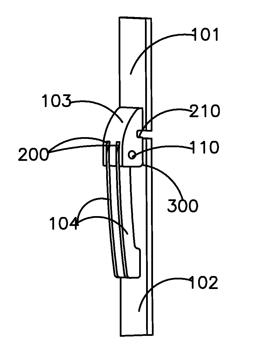
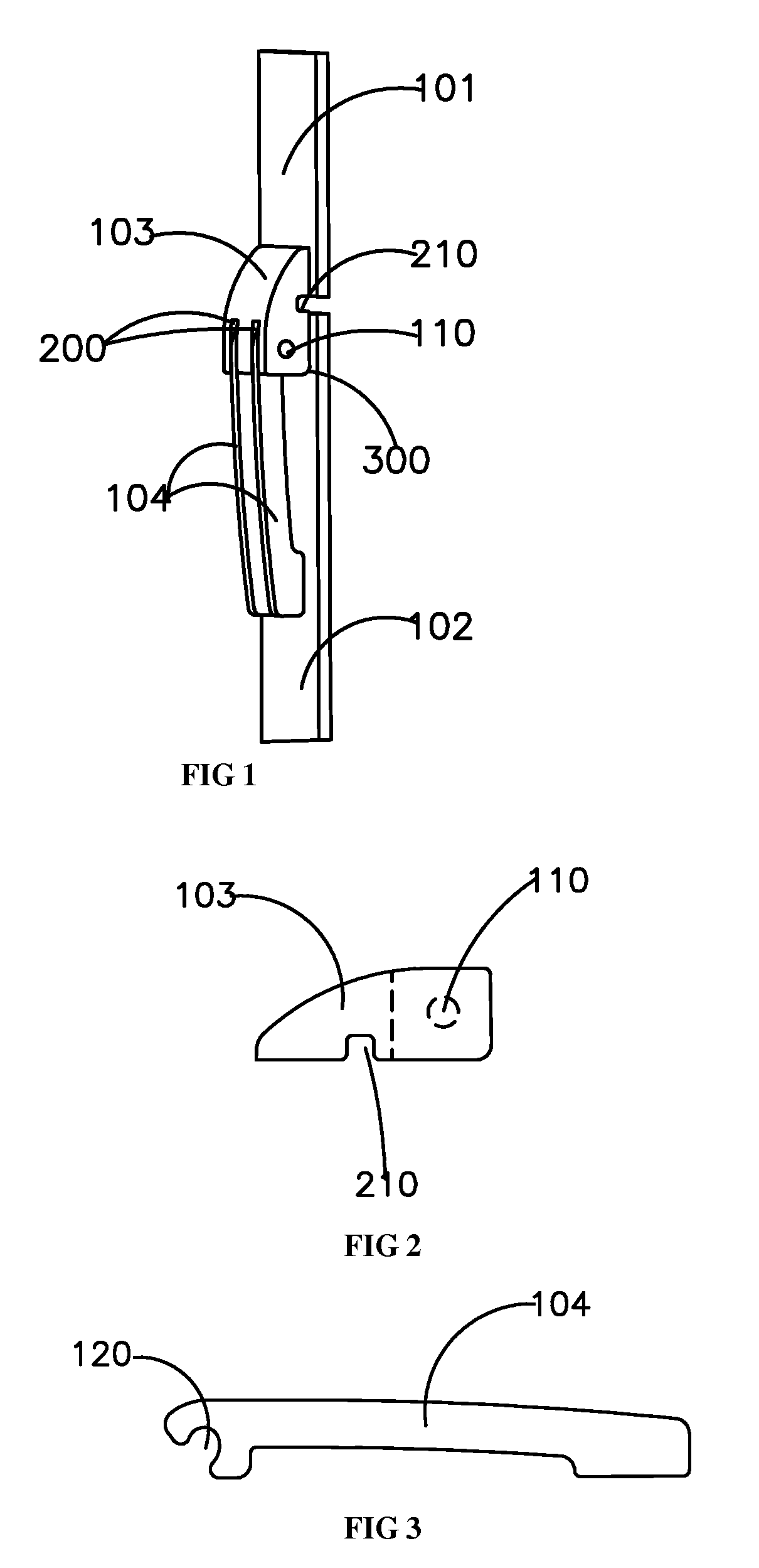
[0024]As shown in FIGS. 1 to 3, the double-pronged flex hinge mechanism for eyeglasses comprises a temple arm 102. An end of said temple arm 102 features two flat springs 104. There is a notch at the end part of the flat spring 104. Said notch 120 hooks onto an axle 110 through a slot 200 on the connecting member 103. Said connecting member 103 has two slots 200, which are meant for the two flat springs 104. The term ‘double pronged’ refers to these two flat springs. The axle 110 passes through the two slots 200 and is fixed on the connecting member 103. The other end of said connecting member 103 is attached to the end piece 101 of the frame front of a eyeglasses frame. The side of said connecting member 103 attached to the end piece 101 features a groove 210. The space created by the groove 210 is a buffer for temple arm 102 when it is opening.

[0025]When the eyeglasses are in use, the hinge mechanism (as shown as 300 in the figure) connecting the temple arm 102 and the connecting ...

embodiment 2

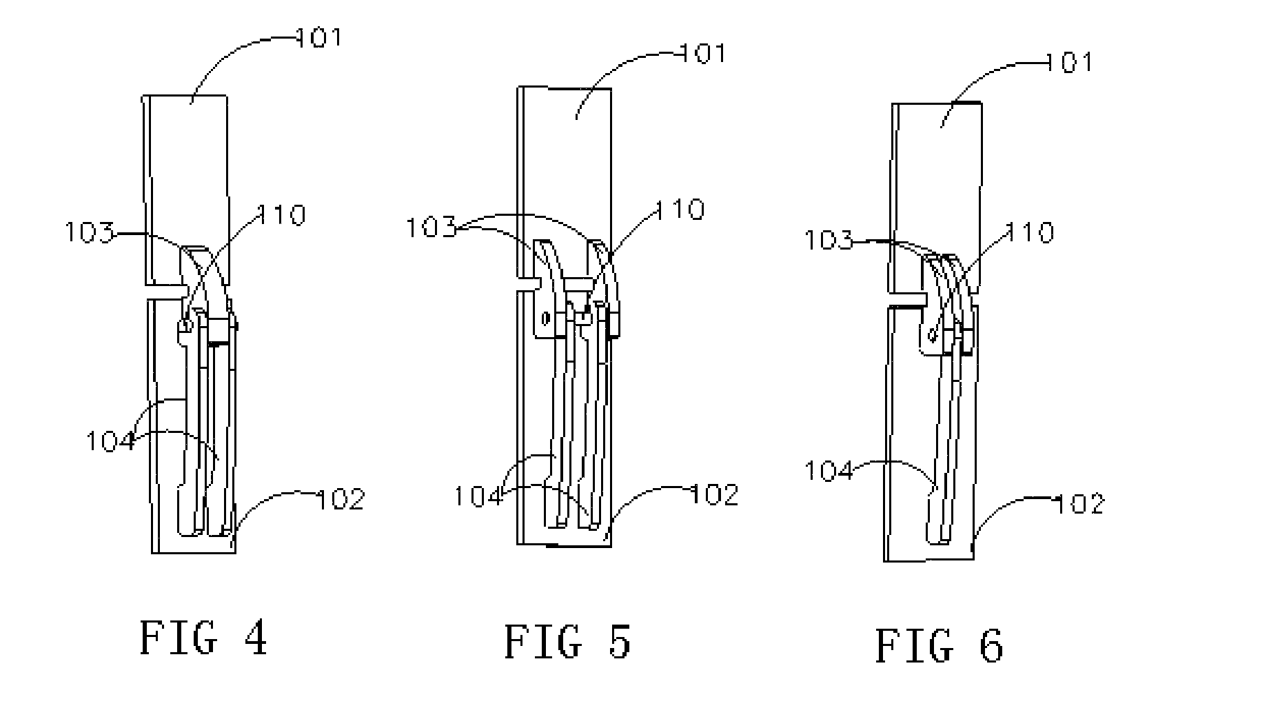
[0026]As shown in FIG. 4, the double-pronged flex hinge mechanism for eyeglasses comprises a temple arm 102. An end of said temple arm 102 features two flat springs 104. There is a notch at the end part of the flat spring 104. The connecting member 103 has an axle 110. Said axle 110 passes through the connecting member 103 and extends to the two sides of the connecting member 103. The notches of the two flat springs 104 hook onto the axle 110 at the two sides of the connecting member 103. The other end of the connecting member 103 is attached to the end piece 101 of the frame front of the eyeglasses.

embodiment 3

[0027]As shown in FIG. 5, the double-pronged flex hinge mechanism for eyeglasses comprises a temple arm 102. An end of said temple arm 102 features flat springs 104. There is a notch at the end part of the flat spring 104. There are two connecting members 103, in between them exists an axle 110. There are two flat springs 104. The notches of the two flat springs 104 hook onto the axle between the two connecting members 103, in between them exists an axle 110. The other end of the connecting member 103 is attached to the end piece 101 of the front frame of the eyeglasses.


PUM


Abstract

The present invention enclosure a double-pronged flex hinge mechanism for eyeglasses frames, provide a safe, reliable, and easy to produce double-pronged flex hinge mechanism for eyeglasses temple arms. A double-pronged flex hinge mechanism comprising a temple arm, provided with a flat spring at one end. The end of said flat spring has a notch, which hooks onto the axle in the connecting members. The other end of said connecting member is attached to the end piece of the front frame of the eyeglasses. The present invention is very convenient in the assembly, high efficiency, reliable and durable.

Description

CROSS-REFERENCE TO RELATED APPLICATIONS[0001]The present application claims priority to Chinese Utility Model Application No. ZL2010 2 0236862.1, filed Jun. 13, 2010, the entirety of which is incorporated herein by reference.FIELD OF THE INVENTION[0002]The present invention relates to a glasses frame, specifically, a double-pronged flex hinge mechanism for eyeglasses frames.BACKGROUND OF THE INVENTION[0003]Most of the modern glasses frames are made of metal with titanium alloys being used for high-end ones. In most of the modern glasses frames, screws are used in hinges which serve for connecting the frame fronts to the temples. Screws, which are vital in the articulation of the frame front and the temples, can easily get loose and fell out, resulting in repair of the glasses before they can be used again and causing inconvenience to the users. Poor in design and technologically backward, the connecting members, which serve for attaching temple arms to frame fronts, of most of the e...

Claims


Application Information

Patent Timeline
Patent Type & Authority Applications(United States)
IPC IPC(8): G02C5/22
CPCG02C2200/22G02C5/2254
Inventor WONG, SZE TUNG
Owner EAGLE INT INDAL
Why Eureka
Try Eureka