Lightwave interference measurement apparatus

a measurement apparatus and lightwave technology, applied in the direction of structural/machine measurement, geometric properties/aberration measurement, instruments, etc., can solve the problem of long measurement time of three-dimensional measuring apparatus, and achieve the effect of shortening the measurement time and shortening the shap

Inactive Publication Date: 2011-12-15
FUJIFILM CORP
View PDF4 Cites 25 Cited by
  • Summary
  • Abstract
  • Description
  • Claims
  • Application Information

AI Technical Summary

Benefits of technology

[0015]According to the lightwave interference measurement apparatus according to the present invention, while the converging measurement light is applied from the interferometric optical system to the test surface, the test surface is continuously or intermittently rotated about the central axis. The applied measurement light is partly reflected from the test surface. This reflected light and the reference light are combined into the interference light, and form the interference fringes. The one-dimensional or two-dimensional image sensor captures the image of the interference fringes at every different rotational position. Based on the images, the shape of the test surface is obtained. The lightwave interference measurement apparatus according to the present invention can take the images of the interference fringes corresponding to the entire test surface in a shorter time than that required by a conventional three-dimensional measuring apparatus, which scans the test surface by a measuring probe. Therefore, it is possible to measure in a short time the shape of the test surface formed of a rotationally symmetric ruled surface.

Problems solved by technology

The three-dimensional measuring apparatus, however, has a problem of long measurement time due to slow scan speed.

Method used


Image

  • Lightwave interference measurement apparatus
  • Lightwave interference measurement apparatus
  • Lightwave interference measurement apparatus

Examples


first embodiment

[0026]

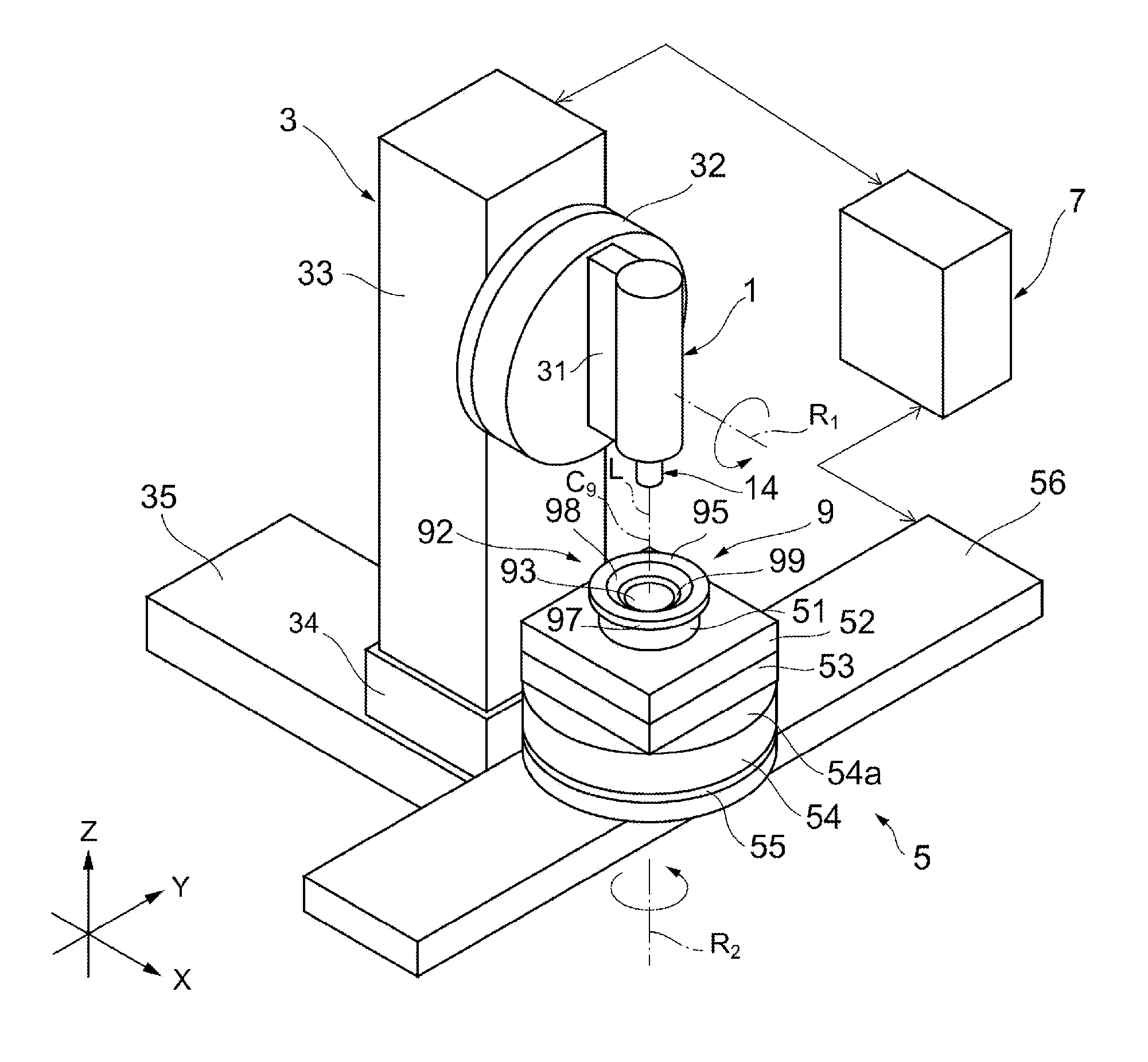
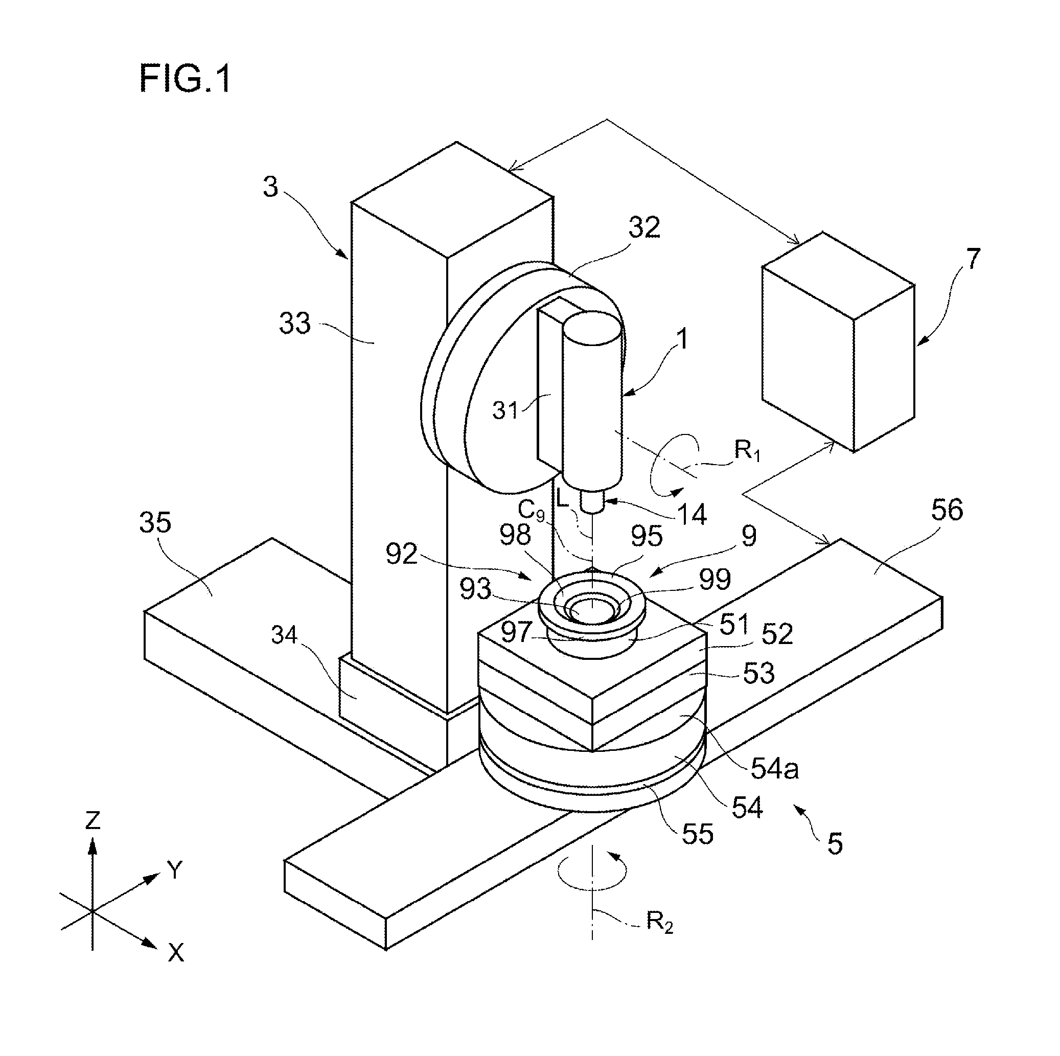
[0027]As shown in FIGS. 6A and 6B, a sample lens 9 is constituted of a lens section 91 and a flange 92 formed on the rim of the lens section 91. The lens section 91 includes an aspheric first lens surface 93 and an aspheric second lens surface 94, both of which are rotationally symmetric about a central axis C9. The flange 92 is in the shape of a ring centered on the central axis C9. A front surface 95 and a rear surface 96 of the flange 92 are orthogonal to the central axis C9. Aside surface 97 of the flange 92 is a circumferential surface centered on the central axis C9.

[0028]A fitting conical surface 98 and a fitting bottom surface 99 are formed between the first lens surface 93 and the front surface 95 of the flange 92. The fitting conical surface 98 is formed of a circular conical surface rotationally symmetric about the central axis C9. The fitting bottom surface 99 is a ring-shaped plane centered on the central axis C9, and is orthogonal to the central axis C9. Note tha...

second embodiment

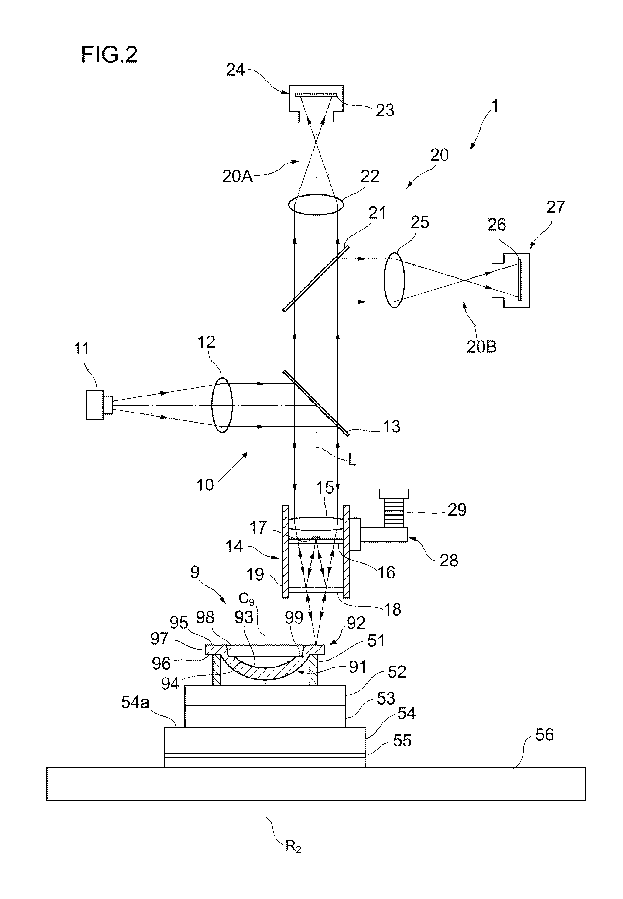
[0084]In the first embodiment, the microinterferometer 1 is provided with the one-dimensional imaging system 20A for taking plural images during rotation of the test surface, and a two-dimensional imaging system 20B for taking an image when the test surface is stopped. A microinterferometer 100 according to a second embodiment, as shown in FIG. 8, is provided only with a two-dimensional imaging system 120. The one-dimensional imaging system 20A captures the images at the established intervals, while the sample lens 9 is continuously rotated, for example. In the second embodiment, the sample lens 9 is intermittently rotated, and the two-dimensional imaging system 120 captures an image while the sample lens 9 is stopped between the intermittent rotational movements. Since the other structure of the microinterferometer 100 is the same as that of the first embodiment, the detailed description thereof is omitted.

[0085]The imaging unit 120 includes an image-forming lens 122 for gathering ...


PUM


Abstract

A microinterferometer applies low coherent measurement light, which travels along an optical axis in a converging manner, to a front surface of a flange. A part of the measurement light is reflected inside an interferometric optical system, and becomes reference light. Apart of the measurement light passed through the interferometric optical system is reflected from the front surface of the flange, and is incident again upon the interferometric optical system. By combining the reflected light with the reference light, interference light is obtained. While a sample rotating stage rotates a sample lens through 360 degrees, a first imaging camera having one-dimensional image sensor captures 3600 images of the interference light, i.e., the image of the interference light is captured every time the sample lens is rotated by 0.1 degrees. Based on the images of interference fringes, the shape of the front surface of the flange is analyzed.

Description

BACKGROUND OF THE INVENTION[0001]1. Field of the Invention[0002]The present invention relates to a lightwave interference measurement apparatus that measures the shape of a test surface based on an image of interference fringes captured by an image sensor.[0003]2. Description Related to the Prior Art[0004]So-called fitting lenses are recently in practical use, for the purpose of allowing the plural lenses to be concentrically aligned along an optical axis direction in a lens barrel. Each of the fitting lenses has a conical fitting surface formed therein. The adjoining plural lenses are fitted to and aligned with each other, using the conical fitting surfaces.[0005]In the fitting lens, the fitting surface requires high formation accuracy, in order to place the individual lenses in proper positions and obtain desired optical performance. Thus, it is required to measure formation errors (errors in an inclination angle, a surface shape, and a diameter) of the fitting surface, and feed t...

Claims


Application Information

Patent Timeline
Patent Type & Authority Applications(United States)
IPC IPC(8): G01B11/02
CPCG01B11/2441G01M11/0271G01M11/025G01M11/0207
Inventor GE, ZONGTAOTOMIMIZU, MASAAKIKANDA, HIDEOIWAZAKI, HIROYUKIKOIZUMI, NOBORUSAITO, TAKAYUKIMOCHITATE, SEIJIOGASAWARA, TAKESHINAKAJIMA, TAKASHI
Owner FUJIFILM CORP
Why Eureka
Try Eureka