
Interference cancellation under non-stationary conditions

a non-stationary condition and interference cancellation technology, applied in the field of wireless communication, can solve the problems of significant deformation of non-coherent estimation, and achieve the effect of boosting the quality of received signals

Inactive Publication Date: 2011-12-15
QUALCOMM INC
View PDF2 Cites 18 Cited by
  • Summary
  • Abstract
  • Description
  • Claims
  • Application Information

AI Technical Summary

Benefits of technology

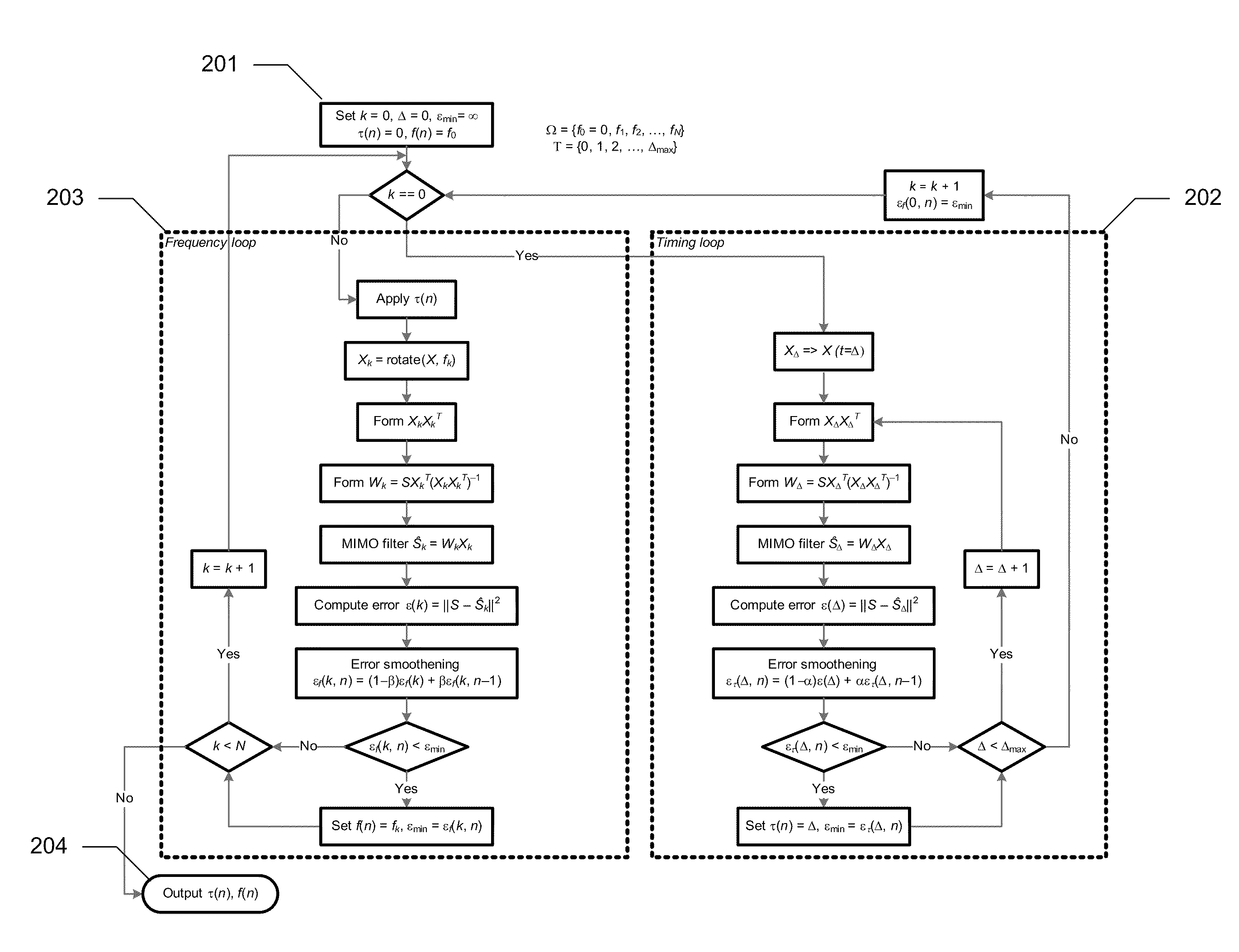
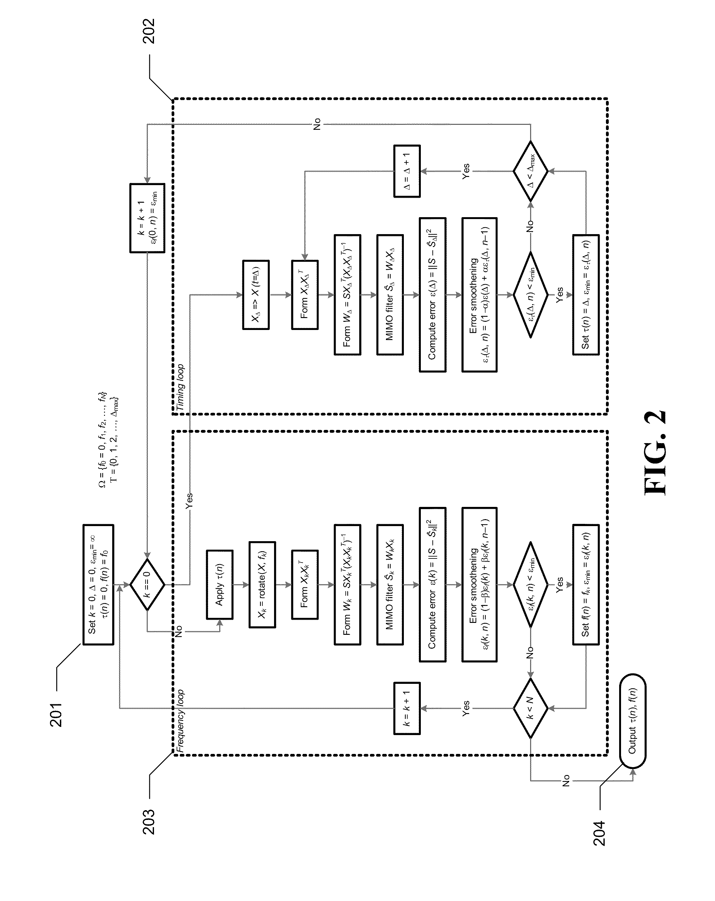
According to certain aspects of the subject technology, an interference suppression filter is tuned to various parameters, and then optimal pairs (of time and frequency) are picked by minimizing the prediction error using a known sequence (midamble or quasi-midamble, e.g., data aided). The algorithm boosts the received signal quality under strong interference whereas non-coherent estimation would degrade significantly.

Problems solved by technology

The algorithm boosts the received signal quality under strong interference whereas non-coherent estimation would degrade significantly.

Method used


Image

  • Interference cancellation under non-stationary conditions
  • Interference cancellation under non-stationary conditions
  • Interference cancellation under non-stationary conditions

Examples


Embodiment Construction

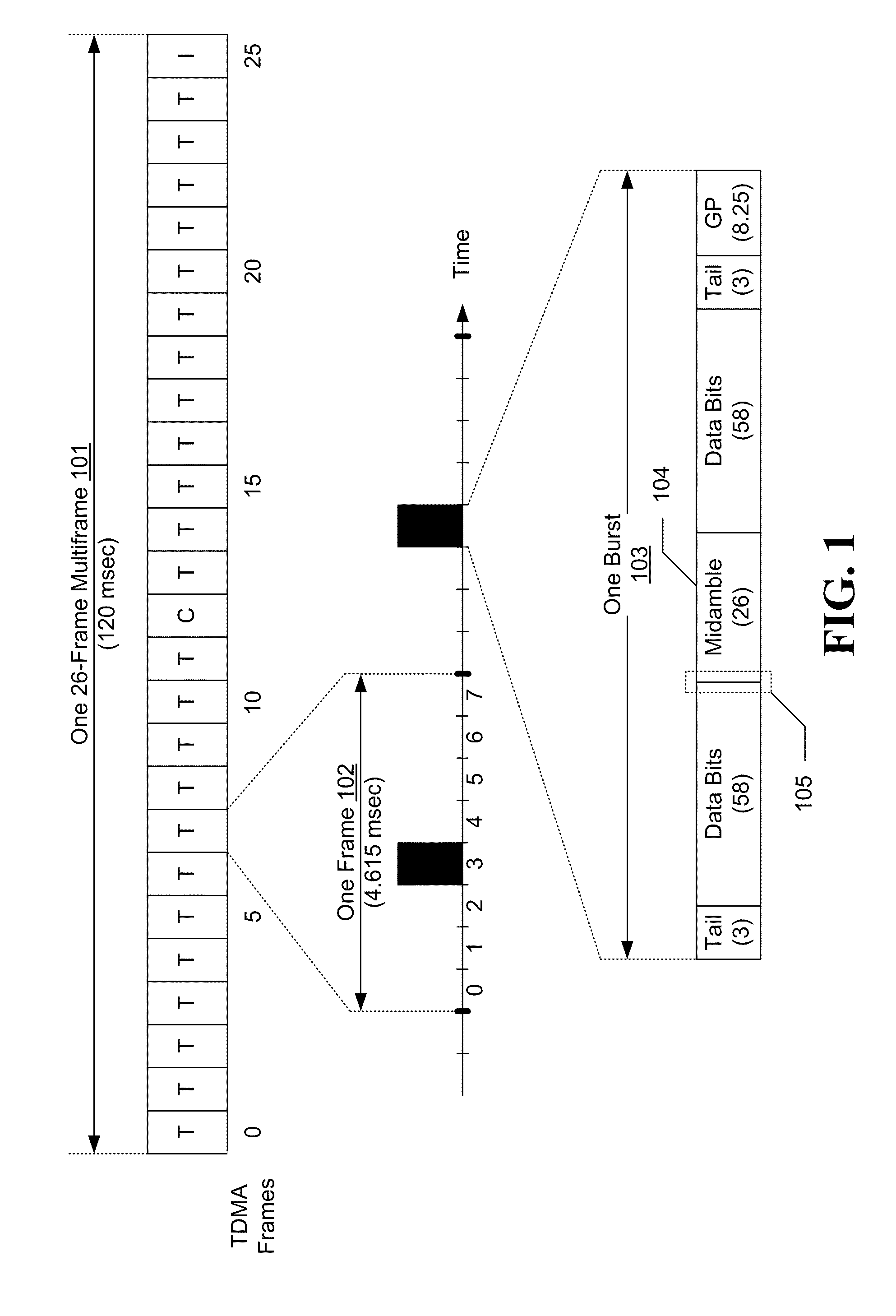
FIG. 1 shows exemplary frame and burst formats in GSM. The timeline for downlink transmission is divided into multiframes. For traffic channels used to send user-specific data, each multiframe, such as exemplary multiframe 101, includes 26 TDMA frames, which are labeled as TDMA frames 0 through 25. The traffic channels are sent in TDMA frames 0 through 11 and TDMA frames 13 through 24 of each multiframe, as identified by the letter “T” in FIG. 1. A control channel, identified by the letter “C,” is sent in TDMA frame 12. No data is sent in the idle TDMA frame 25 (identified by the letter “I”), which is used by the wireless devices to make measurements for neighbor base stations.

Each TDMA frame, such as exemplary TDMA frame 102, is further partitioned into eight time slots, which are labeled as time slots 0 through 7. Each active wireless device / user is assigned one time slot index for the duration of a call. User-specific data for each wireless device is sent in the time slot assigne...


PUM


Abstract

A method for timing and frequency synchronization in a wireless system is provided. The method comprises the steps of receiving a burst of symbols, selecting a subset of the burst of symbols, iteratively adjusting the subset of the burst of symbols by a plurality of timing offsets and calculating, for each timing offset, a first performance metric corresponding to the adjusted subset. The method further comprises the steps of determining one of the plurality of timing offsets to be a preferred timing offset based upon the first performance metric thereof, iteratively rotating the subset of the burst of symbols by a plurality of frequency offsets and calculating, for each frequency offset, a second performance metric corresponding to the rotated subset, and determining one of the plurality of frequency offsets to be a preferred frequency offset based upon the second performance metric thereof.

Description

BACKGROUND1. FieldThe present invention generally relates to wireless communication and, in particular, relates to interference cancellation under non-stationary conditions.2. BackgroundIn many communication systems utilizing GSM, GPRS, EDGE or the like, a receiver's ability to properly decode a received signal depends upon the receiver's ability to accurately estimate symbol timing and frequency. As wireless communications become ever more prevalent, however, increasing amounts of interference can negatively impact a receiver's ability to do so.SUMMARYAccording to one aspect of the subject technology, optimal timing and frequency (by which to rotate the received samples) are jointly obtained in a wireless communication system by parametrizing the subspace into possible timing and frequency hypotheses and searching through them. Joint Max Likelihood of frequency and timing may be performed sequentially or in parallel.According to certain aspects of the subject technology, an interfe...

Claims


Application Information

Patent Timeline
IPC IPC(8): H04B1/10H04L27/06H04B7/02
CPCH04W56/00H04B7/02H04B7/01
Inventor SIKRI, DIVAYDEEPABRISHAMKAR, FARROKHYAN, MINGDE LAURENTIIS, NICO
Owner QUALCOMM INC
Learn More